M20F-FXS, M20G-FXS FUEL FUEL PRESSURE SENSOR(for High Pressure) INSTALLATION
CAUTION / NOTICE / HINT
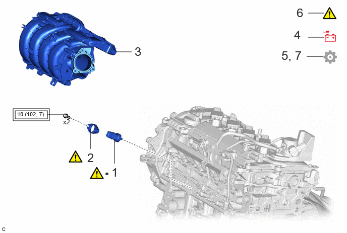
| Procedure | Part Name Code | 
|

|

|
|
|---|---|---|---|---|---|
| 1 | FUEL PRESSURE SENSOR | 89458 | ( 202307,999999,_51,_144959,_0604269,RM100000002BTTI_01_0019,) 202307,999999,_51,_144959,_0604269,RM100000002BTTI_01_0019,)
|
- | - |
| 2 | NO. 1 FUEL PRESSURE SENSOR HOLDER | 23851 | (202307,999999,_51,_144959,_0604269,RM100000002BTTI_01_0018,)
|
- | - |
| 3 | INTAKE MANIFOLD | 17111 | - | - | - |
| 4 | CONNECT CABLE TO NEGATIVE AUXILIARY BATTERY TERMINAL | - | - | - | - |
| 5 | INITIALIZATION AFTER RECONNECTING AUXILIARY BATTERY TERMINAL | - | - | - | (202307,999999,_51,_144959,_0604269,RM100000002BTTI_01_0015,)
|
| 6 | INSPECT FOR FUEL LEAK | - | (202307,999999,_51,_144959,_0604269,RM100000002BTTI_01_0014,)
|
- | - |
| 7 | PERFORM INITIALIZATION | - | - | - | (202307,999999,_51,_144959,_0604269,RM100000002BTTI_01_0013,)
|

|
Tightening torque for "Major areas involving basic vehicle performance such as moving/turning/stopping" : N*m (kgf*cm, ft.*lbf) | ● | Non-reusable part |
CAUTION / NOTICE / HINT
- NOTICE:
-
This procedure includes the installation of small-head bolts. Refer to Small-Head Bolts of Basic Repair Hint to identify the small-head bolts.
PROCEDURE

 89458
1.INSTALL FUEL PRESSURE SENSOR
89458
1.INSTALL FUEL PRESSURE SENSOR
|
|
|

| *a | Cutout (Fuel Delivery Pipe) | *b | Cutout (Fuel Pressure Sensor) |
Temporarily install a new fuel pressure sensor to the fuel delivery pipe as shown in the illustration.
- NOTICE:
-
Make sure that the cutout of the fuel delivery pipe is aligned with the cutout of the fuel pressure sensor.
23851
2.INSTALL NO. 1 FUEL PRESSURE SENSOR HOLDER

| *a | Cutout (Fuel Pressure Sensor) | *b | Cutout (No. 1 Fuel Pressure Sensor Holder) |
Temporarily install the No. 1 fuel pressure sensor holder to the fuel delivery pipe as shown in the illustration.
- NOTICE:
-
Make sure that the cutout of the fuel pressure sensor is aligned with the cutout of the No. 1 fuel pressure sensor holder.
Using an 8 mm socket wrench, install the 2 bolts.
- Torque:
- 10 N*m (102 kgf*cm, 7 ft.*lbf)
17111
3.INSTALL INTAKE MANIFOLD
4.CONNECT CABLE TO NEGATIVE AUXILIARY BATTERY TERMINAL
5. INITIALIZATION AFTER RECONNECTING AUXILIARY BATTERY TERMINAL
- HINT:
-
When disconnecting and reconnecting the auxiliary battery, there is an automatic learning function that completes learning when the respective system is used.
6.INSPECT FOR FUEL LEAK
7.PERFORM INITIALIZATION
Perform "Inspection After Repair" after replacing the fuel pressure sensor.