M20F-FXS, M20G-FXS ENGINE MECHANICAL REAR CRANKSHAFT OIL SEAL INSTALLATION
CAUTION / NOTICE / HINT
- NOTICE:
-
This procedure includes the installation of small-head bolts. Refer to Small-Head Bolts of Basic Repair Hint to identify the small-head bolts.
CAUTION / NOTICE / HINT
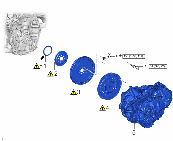
| Procedure | Part Name Code | 
|

|

|
|
|---|---|---|---|---|---|
| 1 | REAR ENGINE OIL SEAL | 11401L | ( 202307,999999,_51,_144958,_0604261,RM100000002BTSV_04_0460,) 202307,999999,_51,_144958,_0604261,RM100000002BTSV_04_0460,)
|
- | - |
| 2 | NO. 1 CRANKSHAFT POSITION SENSOR PLATE | 19315 | (202307,999999,_51,_144958,_0604261,RM100000002BTSV_04_0461,)
|
- | - |
| 3 | FLYWHEEL SUB-ASSEMBLY | 13405 | (202307,999999,_51,_144958,_0604261,RM100000002BTSV_04_0463,)
|
- | - |
| 4 | TRANSMISSION INPUT DAMPER ASSEMBLY | 31270 | (202307,999999,_51,_144958,_0604261,RM100000002BTSV_04_0464,)
|
- | - |
| 5 | HYBRID VEHICLE TRANSAXLE ASSEMBLY | 30900 | - | - | - |

|
N*m (kgf*cm, ft.*lbf): Specified torque | ● | Non-reusable part |

|
MP grease | 
|
Adhesive 1324 |
| ★ | Precoated part | - | - |
PROCEDURE

 11401L
1.INSTALL REAR ENGINE OIL SEAL
11401L
1.INSTALL REAR ENGINE OIL SEAL
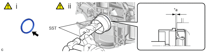
| *a | -0.9 to 1.1 mm | - | - |
Apply MP grease to the lip of a new rear engine oil seal.
- NOTICE:
- ·
Keep the lip free from foreign matter.
·Do not allow MP grease to contact the dust seal.
Using SST and a hammer, tap in the rear engine oil seal.
- SST
- 09223-15030
09950-70010 (09951-07150)
- Standard Depth:
-0.9 to 1.1 mm (-0.0354 to 0.0433 in.) (From the edge of the cylinder block sub-assembly and stiffening crankcase assembly)
- NOTICE:
-
Do not tap in the rear engine oil seal at an angle.
19315
2.INSTALL NO. 1 CRANKSHAFT POSITION SENSOR PLATE
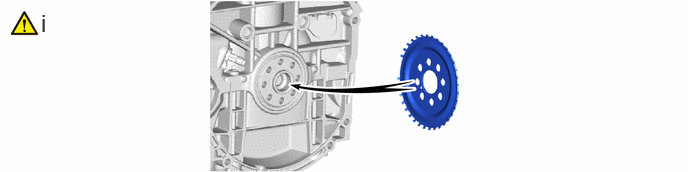
Install the No. 1 crankshaft position sensor plate.
- HINT:
-
Align the pin hole of the No. 1 crankshaft position sensor plate with the pin of the crankshaft.
13405
3.INSTALL FLYWHEEL SUB-ASSEMBLY
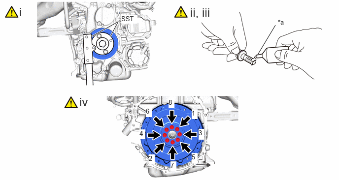
| *a | Adhesive | - |
Using SST, hold the crankshaft pulley assembly.
- SST
- 09213-54015
09330-00021
Clean the bolts and bolt holes.
Apply adhesive to 2 or 3 threads at the end of 8 new bolts.
- Adhesive:
Toyota Genuine Adhesive 1324, Three Bond 1324 or equivalent
Install the flywheel sub-assembly with the 8 bolts. Uniformly tighten the 8 bolts in the order shown in the illustration.
- Torque:
- 150 N*m (1530 kgf*cm, 111 ft.*lbf)
- NOTICE:
-
Do not start the engine for at least 1 hour after installing the flywheel sub-assembly.
31270
4.INSTALL TRANSMISSION INPUT DAMPER ASSEMBLY
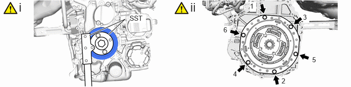
Using SST, hold the crankshaft pulley assembly.
- SST
- 09213-54015
09330-00021
Install the transmission input damper assembly to the flywheel sub-assembly with the 6 bolts. Uniformly tighten the 6 bolts in the order shown in the illustration.
- Torque:
- 30 N*m (306 kgf*cm, 22 ft.*lbf)
- NOTICE:
- ·
Make sure that there are no oil on the transmission input damper assembly and flywheel sub-assembly.
·Make sure to install the transmission input damper assembly in the correct direction.
·Do not allow grease to contact the splines of the transmission input damper assembly and the input shaft.
30900
5.INSTALL HYBRID VEHICLE TRANSAXLE ASSEMBLY