PB10 HYBRID TRANSMISSION / TRANSAXLE HYBRID VEHICLE TRANSAXLE INSTALLATION
CAUTION / NOTICE / HINT
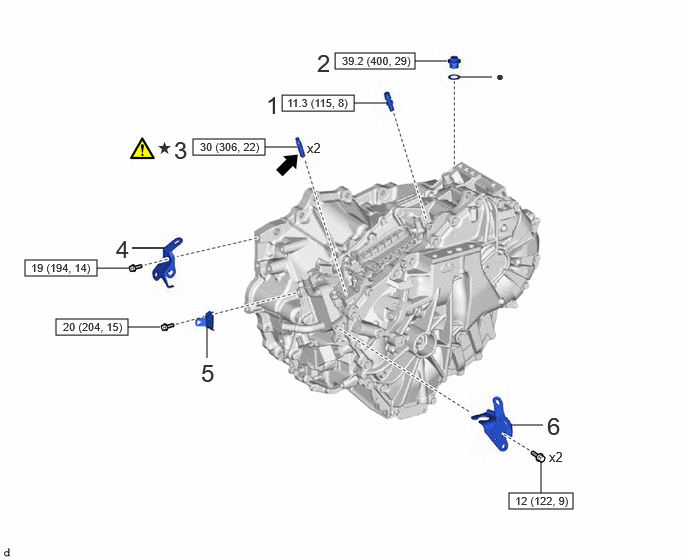
| Procedure | Part Name Code | 
|

|

|
|
|---|---|---|---|---|---|
| 1 | TRANSAXLE BREATHER PLUG | 30900N | - | - | - |
| 2 | TRANSAXLE HOUSING PLUG | - | - | - | - |
| 3 | STUD BOLT | - | ( 202307,999999,_52,_144756,_0603116,RM100000002BO7P_01_0368,) 202307,999999,_52,_144756,_0603116,RM100000002BO7P_01_0368,)
|
- | - |
| 4 | NO. 1 WATER HOSE CLAMP BRACKET | 16575C | - | - | - |
| 5 | WIRE HARNESS CLAMP BRACKET | - | - | - | - |
| 6 | NO. 1 TRANSMISSION CONTROL CABLE BRACKET | 33823 | - | - | - |

|
N*m (kgf*cm, ft.*lbf): Specified torque | ● | Non-reusable part |

|
Toyota Genuine Adhesive 1324, Three Bond 1324 or equivalent | ★ | Precoated part |
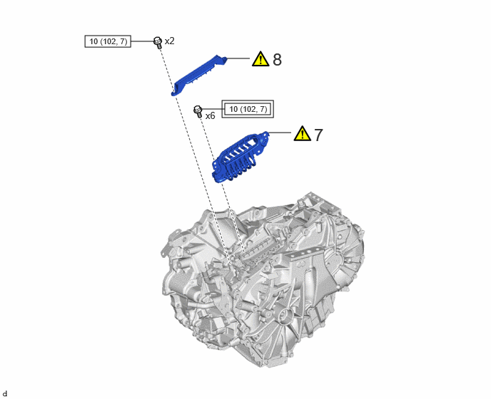
| Procedure | Part Name Code |
|
|
|
|
|---|---|---|---|---|---|
| 7 | MOTOR CABLE | G1148 | (202307,999999,_52,_144756,_0603116,RM100000002BO7P_01_0364,)
|
- | - |
| 8 | TERMINAL CAP | 82823M | (202307,999999,_52,_144756,_0603116,RM100000002BO7P_01_0376,)
|
- | - |

|
Tightening torque for "Major areas involving basic vehicle performance such as moving/turning/stopping": N*m (kgf*cm, ft.*lbf) |
|
N*m (kgf*cm, ft.*lbf): Specified torque |
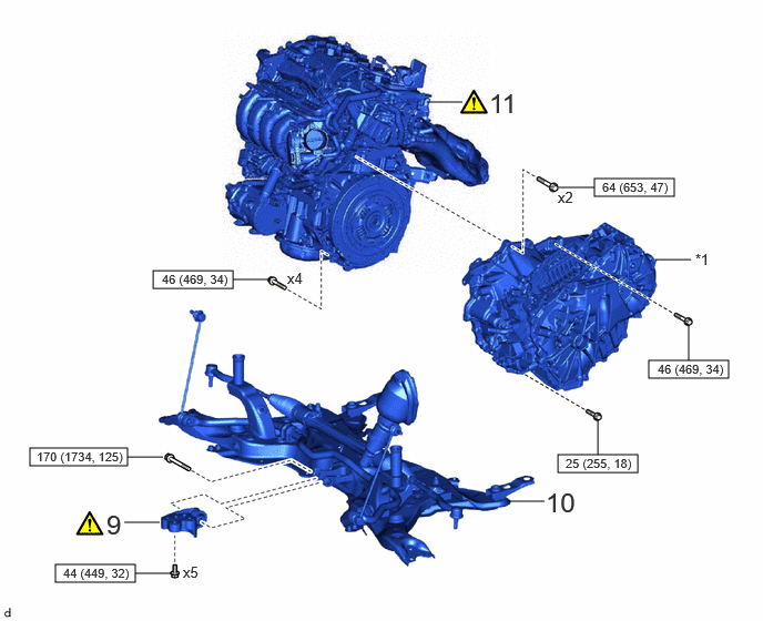
| Procedure | Part Name Code |
|
|
|
|
|---|---|---|---|---|---|
| 9 | NO. 2 ENGINE MOVING CONTROL ROD | 12364B | (202307,999999,_52,_144756,_0603116,RM100000002BO7P_01_0338,)
|
- | - |
| 10 | FRONT SUSPENSION CROSSMEMBER SUB-ASSEMBLY | 51201 | - | - | - |
| 11 | ENGINE ASSEMBLY | - | (202307,999999,_52,_144756,_0603116,RM100000002BO7P_01_0340,)
|
- | - |
| *1 | HYBRID VEHICLE TRANSAXLE ASSEMBLY | - | - |
|
|
N*m (kgf*cm, ft.*lbf): Specified torque | - | - |
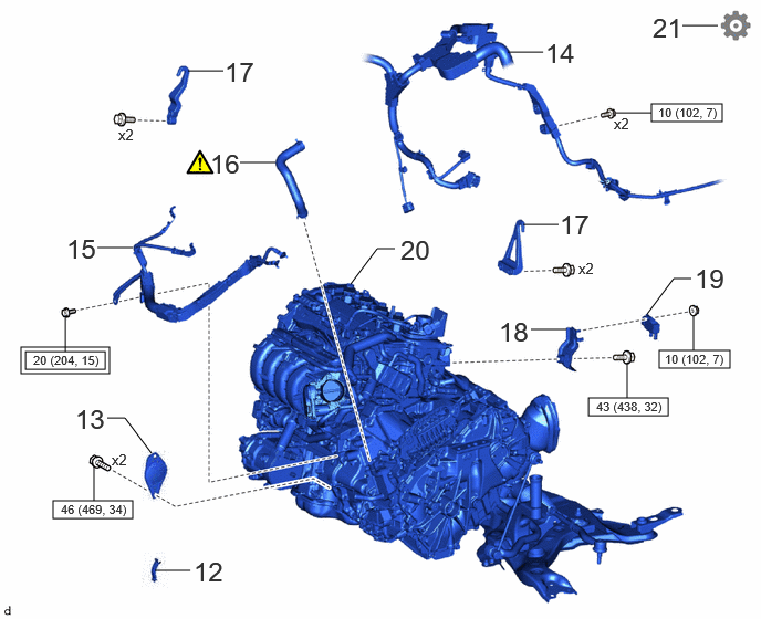
| Procedure | Part Name Code |
|
|
|
|
|---|---|---|---|---|---|
| 12 | FLYWHEEL HOUSING SIDE COVER | 11363A | - | - | - |
| 13 | STARTER HOLE INSULATOR | 28193 | - | - | - |
| 14 | ENGINE WIRE | 82121 | - | - | - |
| 15 | NO. 7 ENGINE WIRE | 82127D | - | - | - |
| 16 | OUTLET NO. 1 INVERTER COOLING HOSE | G922C | (202307,999999,_52,_144756,_0603116,RM100000002BO7P_01_0382,)
|
- | - |
| 17 | ENGINE HANGERS | - | - | - | - |
| 18 | EMISSION CONTROL VALVE BRACKET | - | - | - | - |
| 19 | DIFFERENTIAL PRESSURE SENSOR | 89481B | - | - | - |
| 20 | ENGINE ASSEMBLY WITH TRANSAXLE | - | - | - | - |
| 21 | PERFORM RESOLVER LEARNING | - | - | - | (202307,999999,_52,_144756,_0603116,RM100000002BO7P_01_0366,)
|
|
|
Tightening torque for "Major areas involving basic vehicle performance such as moving/turning/stopping": N*m (kgf*cm, ft.*lbf) |
|
N*m (kgf*cm, ft.*lbf): Specified torque |
CAUTION / NOTICE / HINT
- CAUTION:
-
The engine assembly with hybrid vehicle transaxle assembly is very heavy. Be sure to follow the procedure described in the repair manual, or the engine lifter may suddenly drop.
PROCEDURE

 30900N
1.INSTALL TRANSAXLE BREATHER PLUG
30900N
1.INSTALL TRANSAXLE BREATHER PLUG
- HINT:
-
Perform this procedure only when replacement of the transaxle breather plug is necessary.
- Torque:
- 11.3 N*m (115 kgf*cm, 8 ft.*lbf)
2.INSTALL TRANSAXLE HOUSING PLUG
- Torque:
- 39.2 N*m (400 kgf*cm, 29 ft.*lbf)
3.INSTALL STUD BOLT
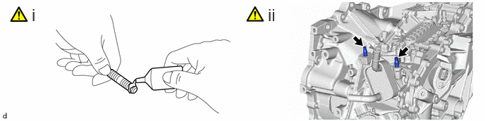
Apply adhesive to the 2 stud bolts.
- Adhesive:
Toyota Genuine Adhesive 1324, Three Bond 1324 or equivalent
Using an E10 "TORX" socket wrench, install the 2 stud bolts to the hybrid vehicle transaxle assembly.
- Torque:
- 30 N*m (306 kgf*cm, 22 ft.*lbf)
16575C
4.INSTALL NO. 1 WATER HOSE CLAMP BRACKET
- Torque:
- 19 N*m (194 kgf*cm, 14 ft.*lbf)
5.INSTALL WIRE HARNESS CLAMP BRACKET
- Torque:
- 20 N*m (204 kgf*cm, 15 ft.*lbf)
33823
6.INSTALL NO. 1 TRANSMISSION CONTROL CABLE BRACKET
- Torque:
- 12 N*m (122 kgf*cm, 9 ft.*lbf)
G1148
7.INSTALL MOTOR CABLE
82823M
8.INSTALL TERMINAL CAP
12364B
9.INSTALL NO. 2 ENGINE MOVING CONTROL ROD
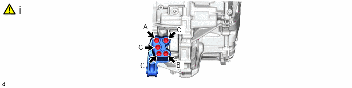
Install the No. 2 engine moving control rod to the hybrid vehicle transaxle assembly with the 5 bolts.
- Torque:
- 44 N*m (449 kgf*cm, 32 ft.*lbf)
- NOTICE:
-
Temporarily tighten the bolt (A), and then fully tighten the 5 bolts in the order of (B), (C) and (A).
51201
10.INSTALL FRONT SUSPENSION CROSSMEMBER SUB-ASSEMBLY
- Torque:
- 170 N*m (1734 kgf*cm, 125 ft.*lbf)
11.INSTALL ENGINE ASSEMBLY
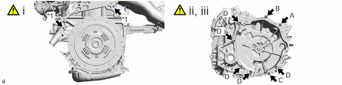
| *1 | Knock Pin | - | - |
Make sure that the knock pins are installed to the engine assembly.
Align the knock pins with the holes in the hybrid vehicle transaxle assembly and, while keeping the contact surfaces of the engine assembly and hybrid vehicle transaxle assembly in close contact with one another, temporarily install the bolt (A).
- NOTICE:
- ·
When tightening the bolts, be sure that the contact surfaces of the engine assembly and hybrid vehicle transaxle assembly are in close contact with one another.
·Do not apply grease to the inner splines of the transmission input damper assembly or input shaft assembly.
·Make sure that the wire harness or similar items are not pinched between the contact surfaces.
·Do not use excessive force when installing the engine assembly.
·Make sure to align the hybrid vehicle transaxle assembly so that the input shaft assembly of the hybrid vehicle transaxle assembly will be inserted straight into the inner splines of the transmission input damper assembly.
·When inserting the input shaft assembly of the hybrid vehicle transaxle assembly into the inner splines of the transmission input damper assembly, do not shake the engine assembly excessively.
·When installing the engine assembly to the hybrid vehicle transaxle assembly, make sure to securely fit the knock pins into the knock pin holes.
While keeping the contact surfaces of the engine assembly and hybrid vehicle transaxle assembly in close contact with one another, install the 8 bolts.
- Torque:
- Bolt (A), (B) : 64 N*m (653 kgf*cm, 47 ft.*lbf)
- Bolt (C) : 25 N*m (255 kgf*cm, 18 ft.*lbf)
- Bolt (D) : 46 N*m (469 kgf*cm, 34 ft.*lbf)
| Bolt | Bolt Length |
|---|---|
| (A), (B) | 50 mm (1.97 in.) |
| (C) | 35 mm (1.38 in.) |
| (D) | 45 mm (1.77 in.) |
11363A
12.INSTALL FLYWHEEL HOUSING SIDE COVER
28193
13.INSTALL STARTER HOLE INSULATOR
- Torque:
- 46 N*m (469 kgf*cm, 34 ft.*lbf)
82121
14.CONNECT ENGINE WIRE
- Torque:
- 10 N*m (102 kgf*cm, 7 ft.*lbf)
82127D
15.INSTALL NO. 7 ENGINE WIRE
- Torque:
- 20 N*m (204 kgf*cm, 15 ft.*lbf)
G922C
16.INSTALL OUTLET NO. 1 INVERTER COOLING HOSE

| *a | Paint Mark | *b | 2 to 11 mm (0.0787 to 0.433 in.) |
| *c | 115° | *d | 275° (Claw of Clip Location) |
Install the outlet No. 1 inverter cooling hose to the motor cooling cooler and slide the clip to secure it.
- NOTICE:
- ·
Make sure to slide the outlet No. 1 inverter cooling hose until it contacts the hose stopper of the motor cooling cooler.
·Make sure to align the paint mark of the outlet No. 1 inverter cooling hose with the paint mark of the motor cooling cooler.
·Make sure that the claws of the clip are within the location shown in the illustration.
17.REMOVE ENGINE HANGERS
18.INSTALL EMISSION CONTROL VALVE BRACKET
89481B
19.INSTALL DIFFERENTIAL PRESSURE SENSOR
20.INSTALL ENGINE ASSEMBLY WITH TRANSAXLE
21. PERFORM RESOLVER LEARNING
- NOTICE:
-
If the hybrid vehicle transaxle assembly has been replaced, make sure to perform resolver learning.