M20F-FXS, M20G-FXS ENGINE MECHANICAL CAMSHAFT INSTALLATION
CAUTION / NOTICE / HINT
- NOTICE:
-
This procedure includes the installation of small-head bolts. Refer to Small-Head Bolts of Basic Repair Hint to identify the small-head bolts.
CAUTION / NOTICE / HINT
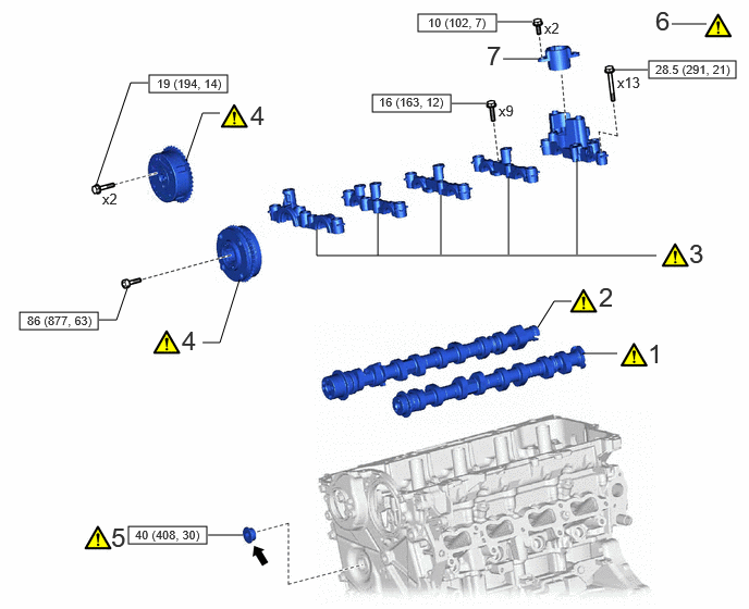
| Procedure | Part Name Code | 
|

|

|
|
|---|---|---|---|---|---|
| 1 | EXHAUST CAMSHAFT SUB-ASSEMBLY | - | ( 202307,999999,_51,_144958,_0604258,RM100000002BTSQ_02_0193,) 202307,999999,_51,_144958,_0604258,RM100000002BTSQ_02_0193,)
|
- | - |
| 2 | INTAKE CAMSHAFT SUB-ASSEMBLY | - | (202307,999999,_51,_144958,_0604258,RM100000002BTSQ_02_0199,)
|
- | - |
| 3 | CAMSHAFT BEARING CAP | - | (202307,999999,_51,_144958,_0604258,RM100000002BTSQ_02_0198,)
|
- | - |
| 4 | CAMSHAFT TIMING GEAR ASSEMBLY | - | (202307,999999,_51,_144958,_0604258,RM100000002BTSQ_02_0197,)
|
- | - |
| 5 | STRAIGHT SCREW PLUG | - | (202307,999999,_51,_144958,_0604258,RM100000002BTSQ_02_0194,)
|
- | - |
| 6 | SET NO. 1 CYLINDER TO TDC (COMPRESSION) | - | (202307,999999,_51,_144958,_0604258,RM100000002BTSQ_02_0195,)
|
- | - |
| 7 | FUEL PUMP LIFTER GUIDE | 23477 | - | - | - |

|
N*m (kgf*cm, ft.*lbf): Specified torque | 
|
Adhesive 1324 |
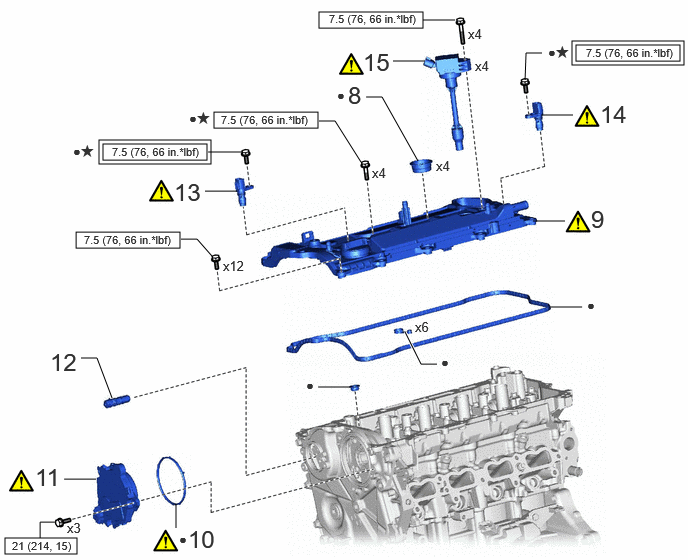
| Procedure | Part Name Code |
|
|
|
|
|---|---|---|---|---|---|
| 8 | SPARK PLUG TUBE GASKET | 11193 | - | - | - |
| 9 | CYLINDER HEAD COVER SUB-ASSEMBLY | 11201 | (202307,999999,_51,_144958,_0604258,RM100000002BTSQ_02_0142,)
|
- | - |
| 10 | CAM TIMING CONTROL MOTOR O-RING | 13090E | (202307,999999,_51,_144958,_0604258,RM100000002BTSQ_02_0146,)
|
- | - |
| 11 | CAM TIMING CONTROL MOTOR WITH EDU ASSEMBLY | 13090D | (202307,999999,_51,_144958,_0604258,RM100000002BTSQ_02_0147,)
|
- | - |
| 12 | CAMSHAFT TIMING OIL CONTROL VALVE ASSEMBLY (EXHAUST CAMSHAFT TIMING GEAR BOLT ASSEMBLY) | - | (202307,999999,_51,_144958,_0604258,RM100000002BTSQ_02_0196,)
|
- | - |
| 13 | CAMSHAFT POSITION SENSOR (for Exhaust Side) | 11102A | (202307,999999,_51,_144958,_0604258,RM100000002BTSQ_02_0201,)
|
- | - |
| 14 | CAMSHAFT POSITION SENSOR (for Intake Side) | 11102A | (202307,999999,_51,_144958,_0604258,RM100000002BTSQ_02_0200,)
|
- | - |
| 15 | IGNITION COIL ASSEMBLY | 19500 | (202307,999999,_51,_144958,_0604258,RM100000002BTSQ_02_0123,)
|
- | - |

|
Tightening torque for "Major areas involving basic vehicle performance such as moving/turning/stopping" : N*m (kgf*cm, ft.*lbf) |
|
N*m (kgf*cm, ft.*lbf): Specified torque |
| ● | Non-reusable part | ★ | Precoated part |
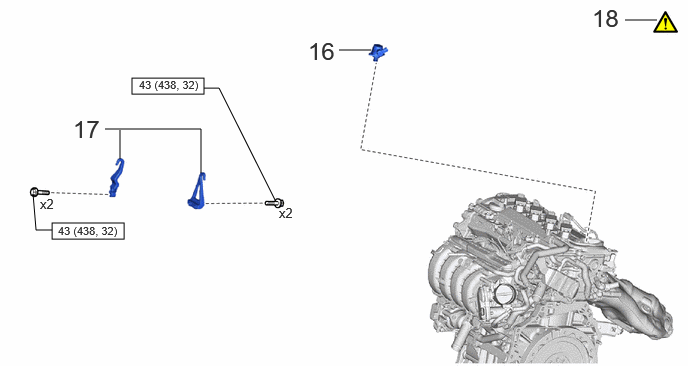
| Procedure | Part Name Code |
|
|
|
|
|---|---|---|---|---|---|
| 16 | FUEL (ENGINE ROOM SIDE) PUMP ASSEMBLY | 23100X | - | - | - |
| 17 | ENGINE HANGERS | - | (202307,999999,_51,_144958,_0604258,RM100000002BTSQ_02_0166,)
|
- | - |
| 18 | ENGINE ASSEMBLY FROM ENGINE STAND | - | (202307,999999,_51,_144958,_0604258,RM100000002BTSQ_02_0167,)
|
- | - |
|
|
N*m (kgf*cm, ft.*lbf): Specified torque | - | - |
PROCEDURE

 1.INSTALL EXHAUST CAMSHAFT SUB-ASSEMBLY
|
|
|
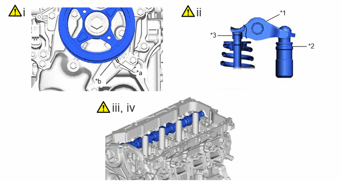
| *1 | No. 1 Valve Rocker Arm Sub-assembly | *2 | Valve Lash Adjuster Assembly |
| *3 | Valve Stem Cap | - | - |
| *a | "0" Timing Mark | *b | Timing Mark |
Turn the crankshaft clockwise to align the timing mark (cutout) on the crankshaft pulley assembly with the "0" timing mark on the No. 2 timing chain cover assembly.
Check that the No. 1 valve rocker arm sub-assembly is correctly installed as shown in the illustration.
Clean the camshaft housing sub-assembly and the cams and journals of the intake camshaft sub-assembly and exhaust camshaft sub-assembly, and then apply engine oil to them.
Apply a light coat of engine oil to the journals of the exhaust camshaft sub-assembly and install the exhaust camshaft sub-assembly to the camshaft housing sub-assembly.
2.INSTALL INTAKE CAMSHAFT SUB-ASSEMBLY

Clean the camshaft housing sub-assembly and the cams and journals of the intake camshaft sub-assembly, and then apply engine oil to them.
Apply a light coat of engine oil to the journals of the intake camshaft sub-assembly and install the intake camshaft sub-assembly to the camshaft housing sub-assembly.
3.INSTALL CAMSHAFT BEARING CAP
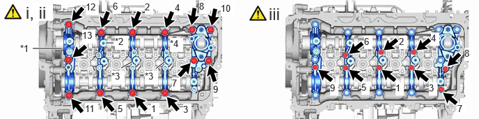
| *1 | No. 1 Camshaft Bearing Cap | *2 | No. 2 Camshaft Bearing Cap |
| *3 | No. 3 Camshaft Bearing Cap | *4 | No. 4 Camshaft Bearing Cap |
Set the No. 1 camshaft bearing cap, No. 2 camshaft bearing cap, 2 No. 3 camshaft bearing caps and No. 4 camshaft bearing cap as shown in the illustration.
Uniformly tighten the 13 bolts in the order shown in the illustration.
- Torque:
- 28.5 N*m (291 kgf*cm, 21 ft.*lbf)
Uniformly tighten the 9 bolts in the order shown in the illustration.
- Torque:
- 16 N*m (163 kgf*cm, 12 ft.*lbf)
4.INSTALL CAMSHAFT TIMING GEAR ASSEMBLY
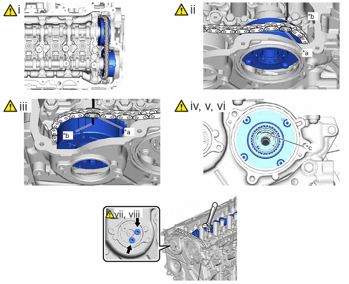
| *a | Paint Mark | *b | Timing Mark |
| *c | Knock Pin | - | - |
Set the camshaft timing gear assembly and camshaft timing exhaust gear assembly to the chain sub-assembly as shown in the illustration.
Align the timing mark on the camshaft timing gear assembly with the paint mark on the chain sub-assembly.
Align the timing mark on the camshaft timing exhaust gear assembly with the paint mark on the chain sub-assembly.
Using the hexagonal portion of the intake camshaft sub-assembly, install the camshaft timing gear assembly to the intake camshaft sub-assembly.
Check that the knock pin matches the pin hole from the No. 2 timing chain cover sub-assembly side.
Using a 10 mm bi-hexagon socket wrench, temporarily install the camshaft timing gear assembly with the bolt.
- HINT:
-
Temporarily install the bolt enough that the camshaft timing gear assembly does not detach from the knock pin of the intake camshaft sub-assembly.
Using the hexagonal portion of the exhaust camshaft sub-assembly, install the camshaft timing exhaust gear assembly to the exhaust camshaft sub-assembly.
Temporarily install the 2 bolts.
- HINT:
-
The 2 bolts can only be installed as shown in the illustration if the knock pin on the exhaust camshaft sub-assembly and the pin hole on the camshaft timing exhaust gear assembly match. If the 2 bolts cannot be installed, the knock pin and pin hole do not match.
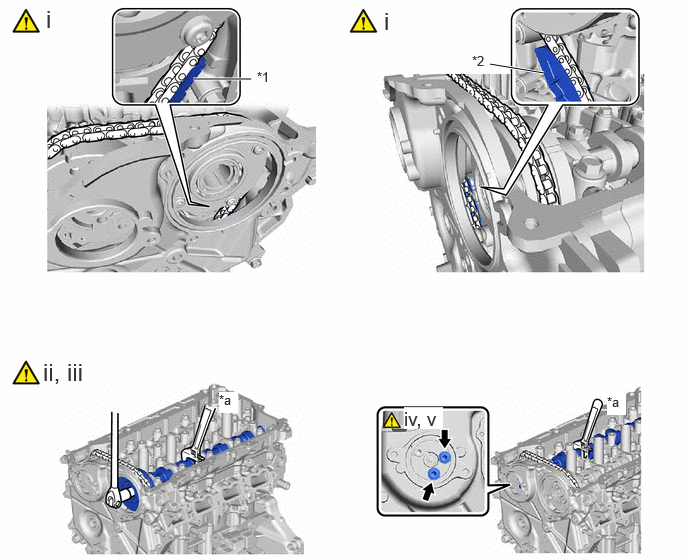
| *1 | No. 1 Chain Vibration Damper | *2 | Chain Tensioner Slipper |
| *a | Hold | - | - |
Check the status of the camshaft timing gear assembly and camshaft timing exhaust gear assembly temporarily installed to each camshaft.
Camshaft timing gear assembly side:
Check that the chain sub-assembly does not overlap the No. 1 chain vibration damper as shown in the illustration.
- NOTICE:
-
If the chain sub-assembly overlaps the No. 1 chain vibration damper, install it again.
Camshaft timing exhaust gear assembly side:
Check that the chain sub-assembly does not overlap the chain tensioner slipper as shown in the illustration.
- NOTICE:
-
If the chain sub-assembly overlaps the chain tensioner slipper, install it again.
Using the hexagonal portion of the intake camshaft sub-assembly, hold the intake camshaft sub-assembly.
- NOTICE:
- ·
Do not damage the camshaft housing sub-assembly, cylinder head sub-assembly and spark plug tube.
·Do not disassemble the camshaft timing gear assembly.
Using a 10 mm bi-hexagon socket wrench, tighten the bolt on the camshaft timing gear assembly.
- Torque:
- 86 N*m (877 kgf*cm, 63 ft.*lbf)
Using the hexagonal portion of the exhaust camshaft sub-assembly, hold the exhaust camshaft sub-assembly.
- NOTICE:
-
Do not damage the camshaft housing sub-assembly, cylinder head sub-assembly and spark plug tube.
Using a 5 mm hexagon wrench, tighten the 2 bolts.
- Torque:
- 19 N*m (194 kgf*cm, 14 ft.*lbf)
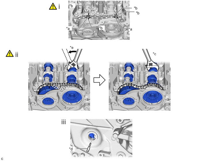
| *a | Paint Mark | *b | Timing Mark |
| *c | Hold | *d | Pin |
| *e | Turn | - | - |
Check that the paint marks and timing marks are positioned as shown in the illustration.
Using the hexagonal portion of the intake camshaft sub-assembly, check that the chain sub-assembly slackens when the intake camshaft sub-assembly is moved in the direction shown in the illustration.
- NOTICE:
-
If the chain sub-assembly remains tight and does not slacken, the chain tensioner slipper and No. 1 chain vibration damper may overlap the chain sub-assembly, so install them again.
Remove the pin from the No. 1 chain tensioner assembly.
5.INSTALL STRAIGHT SCREW PLUG
6.SET NO. 1 CYLINDER TO TDC (COMPRESSION)
23477
7.INSTALL FUEL PUMP LIFTER GUIDE
11193
8.INSTALL SPARK PLUG TUBE GASKET
11201
9.INSTALL CYLINDER HEAD COVER SUB-ASSEMBLY
13090E
10.INSTALL CAM TIMING CONTROL MOTOR O-RING
13090D
11.INSTALL CAM TIMING CONTROL MOTOR WITH EDU ASSEMBLY
12.INSTALL CAMSHAFT TIMING OIL CONTROL VALVE ASSEMBLY (EXHAUST CAMSHAFT TIMING GEAR BOLT ASSEMBLY)
11102A
13.INSTALL CAMSHAFT POSITION SENSOR (for Exhaust Side)
11102A
14.INSTALL CAMSHAFT POSITION SENSOR (for Intake Side)
19500
15.INSTALL IGNITION COIL ASSEMBLY
23100X
16.INSTALL FUEL (ENGINE ROOM SIDE) PUMP ASSEMBLY
17.INSTALL ENGINE HANGERS
18.REMOVE ENGINE ASSEMBLY FROM ENGINE STAND