M20F-FXS, M20G-FXS ENGINE MECHANICAL ENGINE UNIT INSTALLATION
CAUTION / NOTICE / HINT
- NOTICE:
-
This procedure includes the installation of small-head bolts. Refer to Small-Head Bolts of Basic Repair Hint to identify the small-head bolts.
CAUTION / NOTICE / HINT
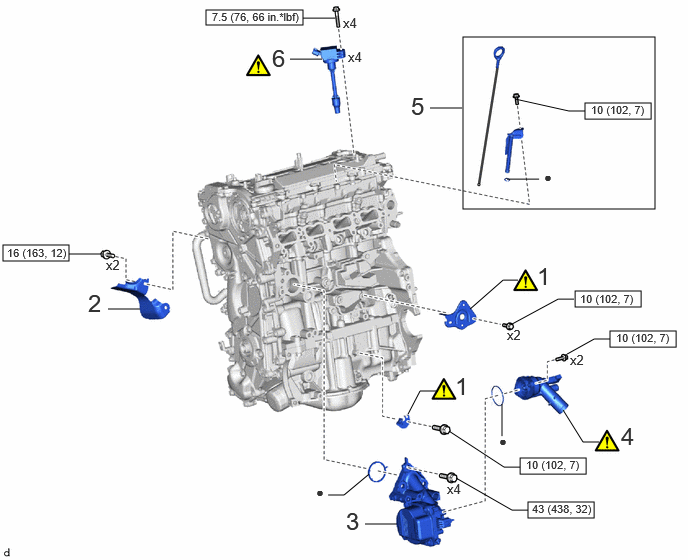
| Procedure | Part Name Code | 
|

|

|
|
|---|---|---|---|---|---|
| 1 | WIRE HARNESS CLAMP BRACKET | - | ( 202307,999999,_51,_144958,_0604254,RM100000002BTSE_01_0115,) 202307,999999,_51,_144958,_0604254,RM100000002BTSE_01_0115,)
|
- | - |
| 2 | NO. 3 EXHAUST MANIFOLD HEAT INSULATOR | 17169A | - | - | - |
| 3 | ENGINE WATER PUMP ASSEMBLY (WATER INLET HOUSING) | 16032 | - | - | - |
| 4 | WATER INLET WITH THERMOSTAT SUB-ASSEMBLY | 16031 | (202307,999999,_51,_144958,_0604254,RM100000002BTSE_01_0046,)
|
- | - |
| 5 | ENGINE OIL LEVEL DIPSTICK GUIDE | 11452D | - | - | - |
| 6 | IGNITION COIL ASSEMBLY | 19500 | (202307,999999,_51,_144958,_0604254,RM100000002BTSE_01_0001,)
|
- | - |
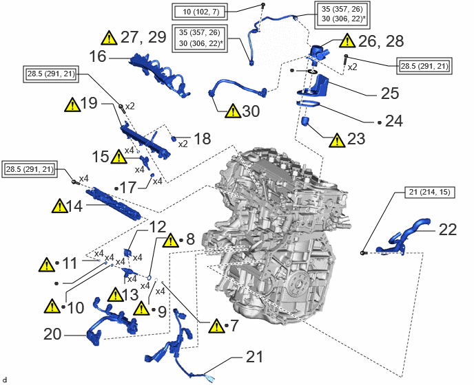
| Procedure | Part Name Code |
|
|
|
|
|---|---|---|---|---|---|
| 7 | INJECTOR SEAL | 23255A | (202307,999999,_51,_144958,_0604254,RM100000002BTSE_01_0113,)
|
- | - |
| 8 | INJECTOR VIBRATION INSULATOR | 23291A | (202307,999999,_51,_144958,_0604254,RM100000002BTSE_01_0127,)
|
- | - |
| 9 | C-RING | - | (202307,999999,_51,_144958,_0604254,RM100000002BTSE_01_0126,)
|
- | - |
| 10 | NO. 1 FUEL INJECTOR BACK-UP RING | 23256 | (202307,999999,_51,_144958,_0604254,RM100000002BTSE_01_0133,)
|
- | - |
| 11 | NO. 3 FUEL INJECTOR BACK-UP RING | 23258 | (202307,999999,_51,_144958,_0604254,RM100000002BTSE_01_0132,)
|
- | - |
| 12 | NOZZLE HOLDER CLAMP | 23695A | - | - | - |
| 13 | DIRECT FUEL INJECTOR ASSEMBLY | 23250E | (202307,999999,_51,_144958,_0604254,RM100000002BTSE_01_0099,)
|
- | - |
| 14 | FUEL DELIVERY PIPE | 23814B | (202307,999999,_51,_144958,_0604254,RM100000002BTSE_01_0084,)
|
- | - |
| 15 | PORT FUEL INJECTOR ASSEMBLY | 23250F | (202307,999999,_51,_144958,_0604254,RM100000002BTSE_01_0098,)
|
- | - |
| 16 | NO. 5 ENGINE WIRE | 82125N | - | - | - |
| 17 | INJECTOR VIBRATION INSULATOR | 23291 | - | - | - |
| 18 | FUEL DELIVERY SPACER | 23891 | - | - | - |
| 19 | FUEL DELIVERY PIPE SUB-ASSEMBLY | 23807 | (202307,999999,_51,_144958,_0604254,RM100000002BTSE_01_0083,)
|
- | - |
| 20 | NO. 6 ENGINE WIRE | 82126A | - | - | - |
| 21 | SENSOR WIRE | 82219C | - | - | - |
| 22 | WATER BY-PASS HOSE ASSEMBLY | - | - | - | - |
| 23 | FUEL PUMP LIFTER ASSEMBLY | 23470 | (202307,999999,_51,_144958,_0604254,RM100000002BTSE_01_0130,)
|
- | - |
| 24 | FUEL PUMP SPACER GASKET | 23224D | - | - | - |
| 25 | FUEL PUMP FLANGE | 23191 | - | - | - |
| 26 | TEMPORARILY INSTALL FUEL (ENGINE ROOM SIDE) PUMP ASSEMBLY (for High Pressure) | 23100X | (202307,999999,_51,_144958,_0604254,RM100000002BTSE_01_0107,)
|
- | - |
| 27 | TEMPORARILY INSTALL NO. 1 FUEL PIPE SUB-ASSEMBLY | 23801P | (202307,999999,_51,_144958,_0604254,RM100000002BTSE_01_0108,)
|
- | - |
| 28 | INSTALL FUEL (ENGINE ROOM SIDE) PUMP ASSEMBLY (for High Pressure) | 23100X | (202307,999999,_51,_144958,_0604254,RM100000002BTSE_01_0088,)
|
- | - |
| 29 | INSTALL NO. 1 FUEL PIPE SUB-ASSEMBLY | 23801P | (202307,999999,_51,_144958,_0604254,RM100000002BTSE_01_0111,)
|
- | - |
| 30 | FUEL TUBE SUB-ASSEMBLY | 23910A | (202307,999999,_51,_144958,_0604254,RM100000002BTSE_01_0112,)
|
- | - |

|
Tightening torque for "Major areas involving basic vehicle performance such as moving/turning/stopping" : N*m (kgf*cm, ft.*lbf) | 
|
N*m (kgf*cm, ft.*lbf): Specified torque |
| ● | Non-reusable part | * | For use with SST |
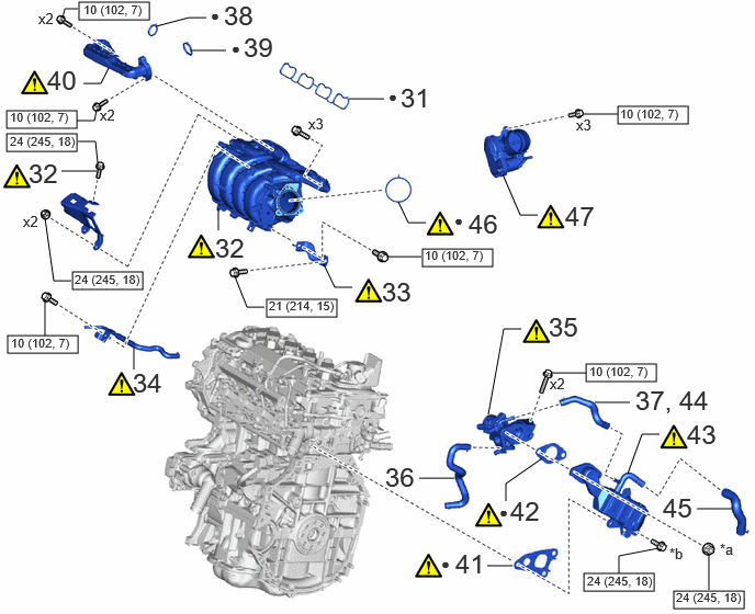
| Procedure | Part Name Code |
|
|
|
|
|---|---|---|---|---|---|
| 31 | NO. 1 INTAKE MANIFOLD TO HEAD GASKET | 17177 | - | - | - |
| 32 | INTAKE MANIFOLD | 17111 | (202307,999999,_51,_144958,_0604254,RM100000002BTSE_01_0006,)
|
- | - |
| 33 | INTAKE MANIFOLD STAY | 17138B | (202307,999999,_51,_144958,_0604254,RM100000002BTSE_01_0119,)
|
- | - |
| 34 | NO. 3 WATER BY-PASS PIPE | 16279 | (202307,999999,_51,_144958,_0604254,RM100000002BTSE_01_0093,)
|
- | - |
| 35 | EGR VALVE ASSEMBLY | 25620 | (202307,999999,_51,_144958,_0604254,RM100000002BTSE_01_0095,)
|
- | - |
| 36 | NO. 8 WATER BY-PASS HOSE | 16296 | - | - | - |
| 37 | NO. 4 WATER BY-PASS HOSE | 16281 | - | - | - |
| 38 | EGR INLET GASKET | 25628 | - | - | - |
| 39 | EGR VALVE ADAPTER GASKET | 25629 | - | - | - |
| 40 | NO. 1 EGR PIPE SUB-ASSEMBLY | 25601 | (202307,999999,_51,_144958,_0604254,RM100000002BTSE_01_0094,)
|
- | - |
| 41 | NO. 1 EGR COOLER GASKET | 25685 | (202307,999999,_51,_144958,_0604254,RM100000002BTSE_01_0142,)
|
- | - |
| 42 | EGR VALVE GASKET | 25627 | (202307,999999,_51,_144958,_0604254,RM100000002BTSE_01_0141,)
|
- | - |
| 43 | EGR COOLER ASSEMBLY | 25680 | (202307,999999,_51,_144958,_0604254,RM100000002BTSE_01_0073,)
|
- | - |
| 44 | NO. 4 WATER BY-PASS HOSE | 16281 | - | - | - |
| 45 | NO. 3 WATER BY-PASS HOSE | 16267 | - | - | - |
| 46 | THROTTLE BODY GASKET | 22271 | (202307,999999,_51,_144958,_0604254,RM100000002BTSE_01_0069,)
|
- | - |
| 47 | THROTTLE BODY WITH MOTOR ASSEMBLY | 22030 | (202307,999999,_51,_144958,_0604254,RM100000002BTSE_01_0051,)
|
- | - |
| *a | x2 or x3 | *b | x3 or x2 |
|
|
N*m (kgf*cm, ft.*lbf): Specified torque | ● | Non-reusable part |
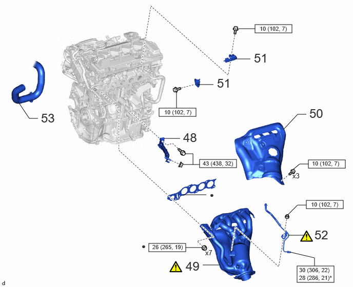
| Procedure | Part Name Code |
|
|
|
|
|---|---|---|---|---|---|
| 48 | MANIFOLD STAY | 17118 | - | - | - |
| 49 | EXHAUST MANIFOLD | 17141 | (202307,999999,_51,_144958,_0604254,RM100000002BTSE_01_0052,)
|
- | - |
| 50 | NO. 1 EXHAUST MANIFOLD HEAT INSULATOR | 17167 | - | - | - |
| 51 | FUEL HOSE BRACKET | 23881B | - | - | - |
| 52 | NO. 1 VACUUM PIPE | 25760 | (202307,999999,_51,_144958,_0604254,RM100000002BTSE_01_0122,)
|
- | - |
| 53 | NO. 2 RADIATOR HOSE | 16572D | - | - | - |
|
|
N*m (kgf*cm, ft.*lbf): Specified torque | ● | Non-reusable part |
| * | For use with Union Nut Wrench | - | - |
PROCEDURE

 1.INSTALL WIRE HARNESS CLAMP BRACKET
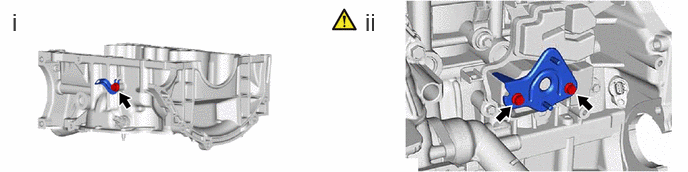
Install the wire harness clamp bracket to the stiffening crankcase assembly with the bolt.
- Torque:
- 10 N*m (102 kgf*cm, 7 ft.*lbf)
Using an 8 mm socket wrench, install the wire harness clamp bracket to the No. 1 ventilation case with the 2 bolts.
- Torque:
- 10 N*m (102 kgf*cm, 7 ft.*lbf)
17169A
2.INSTALL NO. 3 EXHAUST MANIFOLD HEAT INSULATOR
- Torque:
- 16 N*m (163 kgf*cm, 12 ft.*lbf)
16032
3.INSTALL ENGINE WATER PUMP ASSEMBLY (WATER INLET HOUSING)
- Torque:
- 43 N*m (438 kgf*cm, 32 ft.*lbf)
16031
4.INSTALL WATER INLET WITH THERMOSTAT SUB-ASSEMBLY
11452D
5.INSTALL ENGINE OIL LEVEL DIPSTICK GUIDE
- Torque:
- 10 N*m (102 kgf*cm, 7 ft.*lbf)
19500
6.INSTALL IGNITION COIL ASSEMBLY
23255A
7.INSTALL FUEL INJECTOR SEAL
23291A
8.INSTALL INJECTOR VIBRATION INSULATOR
9.INSTALL C-RING
23256
10.INSTALL NO. 1 FUEL INJECTOR BACK-UP RING
23258
11.INSTALL NO. 3 FUEL INJECTOR BACK-UP RING
23695A
12.INSTALL NOZZLE HOLDER CLAMP
23250E
13.INSTALL DIRECT FUEL INJECTOR ASSEMBLY
23814B
14.INSTALL FUEL DELIVERY PIPE
23250F
15.INSTALL PORT FUEL INJECTOR ASSEMBLY
82125N
16.INSTALL NO. 5 ENGINE WIRE
23291
17.INSTALL INJECTOR VIBRATION INSULATOR
23891
18.INSTALL FUEL DELIVERY SPACER
23807
19.INSTALL FUEL DELIVERY PIPE SUB-ASSEMBLY
82126A
20.INSTALL NO. 6 ENGINE WIRE
- Torque:
- 10 N*m (102 kgf*cm, 7 ft.*lbf)
82219C
21.INSTALL SENSOR WIRE
- Torque:
- 10 N*m (102 kgf*cm, 7 ft.*lbf)
22.INSTALL WATER BY-PASS HOSE ASSEMBLY
- Torque:
- 21 N*m (214 kgf*cm, 15 ft.*lbf)
23470
23.INSTALL FUEL PUMP LIFTER ASSEMBLY
23224D
24.INSTALL FUEL PUMP SPACER GASKET
23191
25.SET FUEL PUMP FLANGE
23100X
26.TEMPORARILY INSTALL FUEL (ENGINE ROOM SIDE) PUMP ASSEMBLY (for High Pressure)
23801P
27.TEMPORARILY INSTALL NO. 1 FUEL PIPE SUB-ASSEMBLY
23100X
28.INSTALL FUEL (ENGINE ROOM SIDE) PUMP ASSEMBLY (for High Pressure)
23801P
29.INSTALL NO. 1 FUEL PIPE SUB-ASSEMBLY
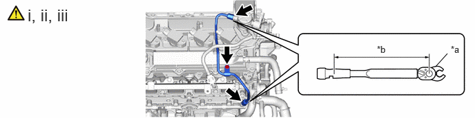
| *a | 17 mm Union Nut Wrench | *b | Torque Wrench Fulcrum Length |
Using a 17 mm union nut wrench, tighten the union nut on the fuel delivery pipe side of the No. 1 fuel pipe sub-assembly.
- Torque:
- Specified tightening torque : 35 N*m (357 kgf*cm, 26 ft.*lbf)
- NOTICE:
-
Do not adjust the torque in the loosening direction.
- HINT:
- ·
Calculate the torque wrench reading when changing the fulcrum length of the torque wrench.
·When using a 17 mm union nut wrench (fulcrum length of 30 mm (1.18 in.)) + torque wrench (fulcrum length of 180 mm (7.09 in.)): 30 N*m (306 kgf*cm, 22 ft.*lbf)
Using a 17 mm union nut wrench, tighten the union nut on the fuel pump assembly side of the No. 1 fuel pipe sub-assembly.
- Torque:
- Specified tightening torque : 35 N*m (357 kgf*cm, 26 ft.*lbf)
- NOTICE:
-
Do not adjust the torque in the loosening direction.
- HINT:
- ·
Calculate the torque wrench reading when changing the fulcrum length of the torque wrench.
·When using a 17 mm union nut wrench (fulcrum length of 30 mm (1.18 in.)) + torque wrench (fulcrum length of 180 mm (7.09 in.)): 30 N*m (306 kgf*cm, 22 ft.*lbf)
Install the bolt.
- Torque:
- 10 N*m (102 kgf*cm, 7 ft.*lbf)
23910A
30.CONNECT FUEL TUBE SUB-ASSEMBLY
Connect the fuel tube sub-assembly to the fuel delivery pipe with sensor assembly.
Install the fuel pipe clamp to the fuel tube connector.
Connect the fuel tube sub-assembly to the fuel pump assembly.
17177
31.INSTALL NO. 1 INTAKE MANIFOLD TO HEAD GASKET
17111
32.INSTALL INTAKE MANIFOLD
17138B
33.INSTALL INTAKE MANIFOLD STAY
16279
34.INSTALL NO. 3 WATER BY-PASS PIPE
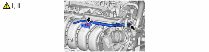
Install the No. 3 water by-pass pipe to the water outlet and slide the clip to secure it.
Using an 8 mm socket wrench, connect the No. 3 water by-pass pipe to the intake manifold with the bolt.
- Torque:
- 10 N*m (102 kgf*cm, 7 ft.*lbf)
25620
35.INSTALL EGR VALVE ASSEMBLY
16296
36.CONNECT NO. 8 WATER BY-PASS HOSE
16281
37.CONNECT NO. 4 WATER BY-PASS HOSE
25628
38.INSTALL EGR INLET GASKET
25629
39.INSTALL EGR VALVE ADAPTER GASKET
25601
40.INSTALL NO. 1 EGR PIPE SUB-ASSEMBLY
25685
41.INSTALL NO. 1 EGR COOLER GASKET
25627
42.INSTALL EGR VALVE GASKET
25680
43.INSTALL EGR COOLER ASSEMBLY
16281
44.CONNECT NO. 4 WATER BY-PASS HOSE
16267
45.CONNECT NO. 3 WATER BY-PASS HOSE
22271
46.INSTALL THROTTLE BODY GASKET
22030
47.INSTALL THROTTLE BODY WITH MOTOR ASSEMBLY
17118
48.INSTALL MANIFOLD STAY
17141
49.INSTALL EXHAUST MANIFOLD
17167
50.INSTALL NO. 1 EXHAUST MANIFOLD HEAT INSULATOR
23211K
51.INSTALL BRACKET
- Torque:
- 10 N*m (102 kgf*cm, 7 ft.*lbf)
25760
52.INSTALL NO. 1 VACUUM PIPE
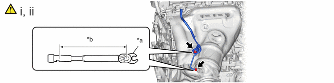
| *a | 14 mm Union Nut Wrench | *b | Torque Wrench Fulcrum Length |
Using a 14 mm union nut wrench, connect the No. 1 vacuum pipe to the exhaust manifold (TWC: Front Catalyst).
- Torque:
- 30 N*m (306 kgf*cm, 22 ft.*lbf)
- HINT:
- ·
Calculate the torque wrench reading when changing the fulcrum length of the torque wrench.
·When using a 10 mm union nut wrench (fulcrum length of 22 mm (0.866 in.)) + torque wrench (fulcrum length of 162 mm (6.38 in.)): 26 N*m (265 kgf*cm, 19 ft.*lbf)
Install the No. 1 vacuum pipe to the exhaust manifold (TWC: Front Catalyst) with the nut.
- Torque:
- 10 N*m (102 kgf*cm, 7 ft.*lbf)
16572D
53.CONNECT NO. 2 RADIATOR HOSE