HYBRID / BATTERY CONTROL HYBRID BATTERY SYSTEM ECU Power Source Circuit
DESCRIPTION
If the ignition switch is ON, the battery ECU assembly applies current to the MREL terminal to turn the IGCT relay on. This supplies power to the IGCT terminals.
WIRING DIAGRAM
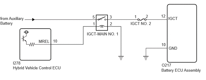
CAUTION / NOTICE / HINT
- CAUTION:
-
Refer to the precautions before inspecting high voltage circuit.
- NOTICE:
- ·
After the ignition switch is turned off, there may be a waiting time before disconnecting the negative (-) auxiliary battery terminal.
·When disconnecting and reconnecting the auxiliary battery
- HINT:
-
When disconnecting and reconnecting the auxiliary battery, there is an automatic learning function that completes learning when the respective system is used.
PROCEDURE
- CAUTION:
-
Be sure to wear insulated gloves and protective goggles.
Check that the service plug grip is not installed.
- NOTICE:
-
After removing the service plug grip, do not turn the ignition switch to ON (READY), unless instructed by the repair manual because this may cause a malfunction.
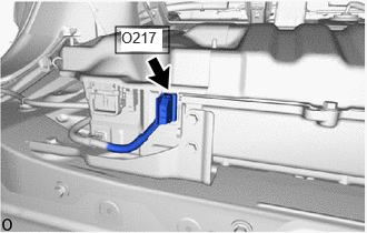
Disconnect the battery ECU assembly connector.
- NOTICE:
-
Before disconnecting the connector, check that it is not loose or disconnected.
Connect the cable to the negative (-) auxiliary battery terminal.
Turn the ignition switch to ON.
Measure the voltage according to the value(s) in the table below.
- Standard Voltage:
Tester Connection Condition Specified Condition O217-12 (IGCT) - Body ground Ignition switch ON 11 to 14 V
- NOTICE:
- ·
Turning the ignition switch to ON with the service plug grip removed causes other DTCs to be stored. Clear the DTCs after performing this inspection.
·If the ignition switch is turned to ON with the connectors disconnected, other DTCs will be stored. Be sure to clear the DTCs after the inspection.
Turn the ignition switch off.
Disconnect the cable from the negative (-) auxiliary battery terminal.
Reconnect the battery ECU assembly connector.
- Result:
Proceed to OK NG
OK
NG
- CAUTION:
-
Be sure to wear insulated gloves and protective goggles.
Check that the service plug grip is not installed.
- NOTICE:
-
After removing the service plug grip, do not turn the ignition switch to ON (READY), unless instructed by the repair manual because this may cause a malfunction.
Disconnect the battery ECU assembly connector.
- NOTICE:
-
Before disconnecting the connector, check that it is not loose or disconnected.
Measure the resistance according to the value(s) in the table below.
- Standard Resistance:
Tester Connection Condition Specified Condition O217-10 (GND) - Body ground Always Below 1 Ω
Reconnect the battery ECU assembly connector.
- Result:
Proceed to OK NG
OK
NG
Remove the IGCT NO. 2 fuse from the No. 1 engine room relay block and No. 1 junction block assembly.
Measure the resistance according to the value(s) in the table below.
- Standard Resistance:
Tester Connection Condition Specified Condition IGCT NO. 2 fuse Always Below 1 Ω
Install the IGCT NO. 2 fuse.
- Result:
Proceed to OK NG
OK
NG
- CAUTION:
-
Be sure to wear insulated gloves and protective goggles.
Check that the service plug grip is not installed.
- NOTICE:
-
After removing the service plug grip, do not turn the ignition switch to ON (READY), unless instructed by the repair manual because this may cause a malfunction.
Disconnect the battery ECU assembly connector.
- NOTICE:
-
Before disconnecting the connector, check that it is not loose or disconnected.
Remove the IGCT NO. 2 fuse from the No. 1 engine room relay block and No. 1 junction block assembly.
Measure the resistance according to the value(s) in the table below.
- Standard Resistance:
Tester Connection Condition Specified Condition O217-12 (IGCT) - 2 (IGCT NO. 2 fuse holder) Always Below 1 Ω
Install the IGCT NO. 2 fuse.
Reconnect the battery ECU assembly connector.
- Result:
Proceed to OK NG
OK
NG
Remove the IGCT-MAIN NO. 1 relay and IGCT NO. 2 fuse from the No. 1 engine room relay block and No. 1 junction block assembly.
Measure the resistance according to the value(s) in the table below.
- Standard Resistance:
Tester Connection Condition Specified Condition 3 (IGCT-MAIN NO. 1 relay holder) - 1 (IGCT NO. 2 fuse holder) Always Below 1 Ω
Install the IGCT-MAIN NO. 1 relay and IGCT NO. 2 fuse.
- Result:
Proceed to OK NG
OK
NG
- CAUTION:
-
Be sure to wear insulated gloves and protective goggles.
Check that the service plug grip is not installed.
- NOTICE:
-
After removing the service plug grip, do not turn the ignition switch to ON (READY), unless instructed by the repair manual because this may cause a malfunction.
Disconnect the battery ECU assembly connector.
- NOTICE:
-
Before disconnecting the connector, check that it is not loose or disconnected.
Remove the IGCT NO. 2 fuse from the No. 1 engine room relay block and No. 1 junction block assembly.
Measure the resistance according to the value(s) in the table below.
- Standard Resistance:
Tester Connection Condition Specified Condition O217-12 (IGCT) or 2 (IGCT NO. 2 fuse holder) - Body ground and other terminals Always 10 kΩ or higher
Install the IGCT NO. 2 fuse.
Reconnect the battery ECU assembly connector.
- Result:
Proceed to OK NG
OK
NG
- Result:
Proceed to NEXT
NEXT