HYBRID / BATTERY CONTROL HYBRID CONTROL SYSTEM ECU Power Source Circuit
DESCRIPTION
If the ignition switch is ON, the hybrid vehicle control ECU applies current to the MREL terminal to turn the IGCT relay on. This supplies power to the +B1 terminal.
WIRING DIAGRAM
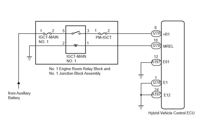
CAUTION / NOTICE / HINT
- NOTICE:
- ·
After the ignition switch is turned off, there may be a waiting time before disconnecting the negative (-) auxiliary battery terminal.
·When disconnecting and reconnecting the auxiliary battery
- HINT:
-
When disconnecting and reconnecting the auxiliary battery, there is an automatic learning function that completes learning when the respective system is used.
PROCEDURE
Turn the ignition switch to ON.
Measure the voltage according to the value(s) in the table below.
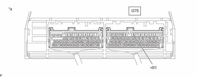
| *a | Component with harness connected
(Hybrid Vehicle Control ECU) |
- | - |
- Standard Voltage:
Tester Connection Condition Specified Condition I278-8 (+B1) - Body ground Ignition switch ON 11 to 14 V
Turn the ignition switch off.
- Result:
Proceed to OK NG
OK
NG
Disconnect the hybrid vehicle control ECU connectors.
Measure the resistance according to the value(s) in the table below.
- Standard Resistance:
Tester Connection Condition Specified Condition A197-12 (E01) - Body ground Always Below 1 Ω A197-24 (E12) - Body ground Always Below 1 Ω I278-1 (E1) - Body ground Always Below 1 Ω
Reconnect the hybrid vehicle control ECU connectors.
- Result:
Proceed to OK NG
OK
NG
Turn the ignition switch to ON.
Measure the voltage according to the value(s) in the table below.

| *a | Component with harness connected
(Hybrid Vehicle Control ECU) |
- | - |
- Standard Voltage:
Tester Connection Condition Specified Condition I278-10 (MREL) - Body ground Ignition switch ON 11 to 14 V
Turn the Ignition switch off.
- Result:
Proceed to OK NG
OK
NG
Remove the PM-IGCT fuse from the No. 1 engine room relay block and No. 1 junction block assembly.
Measure the resistance according to the value(s) in the table below.
- Standard Resistance:
Tester Connection Condition Specified Condition PM-IGCT fuse Always Below 1 Ω
Install the PM-IGCT fuse.
- Result:
Proceed to OK NG
OK
NG
Remove the IGCT-MAIN NO. 1 fuse from the No. 1 engine room relay block and No. 1 junction block assembly.
Measure the resistance according to the value(s) in the table below.
- Standard Resistance:
Tester Connection Condition Specified Condition IGCT-MAIN NO. 1 fuse Always Below 1 Ω
Install the IGCT-MAIN NO. 1 fuse.
- Result:
Proceed to OK NG
OK
NG
Remove the IGCT-MAIN NO. 1 relay from the No. 1 engine room relay block and No. 1 junction block assembly.

| *1 | IGCT-MAIN NO. 1 Relay |
Measure the resistance according to the value(s) in the table below.
- Standard Resistance:
Tester Connection Condition Specified Condition 3 - 5 Auxiliary battery voltage not applied between terminals 1 and 2 10 kΩ or higher Auxiliary battery voltage applied between terminals 1 and 2 Below 1 Ω
Install the IGCT-MAIN NO. 1 relay.
- Result:
Proceed to OK NG
OK
NG
Disconnect the hybrid vehicle control ECU connector.
Remove the PM-IGCT fuse from the No. 1 engine room relay block and No. 1 junction block assembly.
Measure the resistance according to the value(s) in the table below.
- Standard Resistance:
Tester Connection Condition Specified Condition I278-8 (+B1) - 2 (PM-IGCT fuse holder) Always Below 1 Ω
Install the PM-IGCT fuse.
Reconnect the hybrid vehicle control ECU connector.
- Result:
Proceed to OK NG
OK
NG
Remove the IGCT-MAIN NO. 1 fuse, PM-IGCT fuse and IGCT-MAIN NO. 1 relay from the No. 1 engine room relay block and No. 1 junction block assembly.
Measure the resistance according to the value(s) in the table below.
- Standard Resistance:
Tester Connection Condition Specified Condition 5 (IGCT-MAIN NO. 1 relay holder) - 2 (IGCT-MAIN NO. 1 fuse holder) Always Below 1 Ω 3 (IGCT-MAIN NO. 1 relay holder) - 1 (PM-IGCT fuse holder) Always Below 1 Ω
Install the IGCT-MAIN NO. 1 fuse, PM-IGCT fuse and IGCT-MAIN NO. 1 relay.
- Result:
Proceed to OK NG
OK
NG
Disconnect the hybrid vehicle control ECU connector.
Remove the IGCT-MAIN NO. 1 relay from the No. 1 engine room relay block and No. 1 junction block assembly.
Measure the resistance according to the value(s) in the table below.
- Standard Resistance:
Tester Connection Condition Specified Condition I278-10 (MREL) - 1 (IGCT-MAIN NO. 1 relay holder) Always Below 1 Ω I278-10 (MREL) or 1 (IGCT-MAIN NO. 1 relay holder) - Body ground and other terminals Always 10 kΩ or higher
Install the IGCT-MAIN NO. 1 relay.
Reconnect the hybrid vehicle control ECU connector.
- Result:
Proceed to OK NG
OK
NG
Remove the IGCT-MAIN NO. 1 relay from the No. 1 engine room relay block and No. 1 junction block assembly.
Measure the resistance according to the value(s) in the table below.
- Standard Resistance:
Tester Connection Condition Specified Condition 2 (IGCT-MAIN NO. 1 relay holder) - Body ground Always Below 1 Ω
Install the IGCT-MAIN NO. 1 relay.
- Result:
Proceed to OK NG
OK
NG
Remove the PM-IGCT fuse from the No. 1 engine room relay block and No. 1 junction block assembly.
Disconnect the hybrid vehicle control ECU connector.
Measure the resistance according to the value(s) in the table below.
- Standard Resistance:
Tester Connection Condition Specified Condition I278-8 (+B1) or 2 (PM-IGCT fuse holder) - Body ground and other terminals Always 10 kΩ or higher
Reconnect the hybrid vehicle control ECU connector.
Install the PM-IGCT fuse.
- Result:
Proceed to OK NG
OK
NG
Remove the IGCT-MAIN NO. 1 fuse, PM-IGCT fuse and IGCT-MAIN NO. 1 relay from the No. 1 engine room relay block and No. 1 junction block assembly.
Measure the resistance according to the value(s) in the table below.
- Standard Resistance:
Tester Connection Condition Specified Condition 5 (IGCT-MAIN NO. 1 relay holder) or 2 (IGCT-MAIN NO. 1 fuse holder) - Body ground and other terminals Always 10 kΩ or higher 3 (IGCT-MAIN NO. 1 relay holder) or 1 (PM-IGCT fuse holder) - Body ground and other terminals Always 10 kΩ or higher
Install the IGCT-MAIN NO. 1 fuse, PM-IGCT fuse and IGCT-MAIN NO. 1 relay.
- Result:
Proceed to OK NG
OK
NG
- Result:
Proceed to NEXT
NEXT
- Result:
Proceed to NEXT
NEXT