HYBRID / BATTERY CONTROL HYBRID BATTERY SYSTEM P0C3000 Hybrid/EV Battery State of Charge High
DESCRIPTION
The battery ECU assembly monitors the operation of the hybrid battery system and will store this DTC if it detects a malfunction.
| DTC No. | Detection Item | DTC Detection Condition | Trouble Area | MIL | Warning Indicate | Note |
|---|---|---|---|---|---|---|
| P0C3000 | Hybrid/EV Battery State of Charge High | Even though charging of the HV battery is prohibited due to the SOC reaching the upper limit, charging continues to be performed due to a hybrid control system malfunction.
(1 trip detection logic) |
·
Hybrid vehicle control ECU ·
HV battery junction block assembly |
Does not come on | Master Warning:
Comes on |
SAE Code: P0C30 |
CONFIRMATION DRIVING PATTERN
- HINT:
-
After repairs have been completed, clear the DTCs and then check that the vehicle has returned to normal by performing the following All Readiness check procedure.
Connect the GTS to the DLC3.
Turn the ignition switch to ON and turn the GTS on.
Clear the DTCs (even if no DTCs are stored, perform the clear DTC procedure).
Turn the ignition switch off and wait for 2 minutes or more.
Turn the ignition switch to ON and turn the GTS on.
Apply the parking brake and secure the wheels using chocks.
Turn the ignition switch to ON (READY), move the shift lever to D and the vehicle stopped, firmly depress the brake pedal and accelerator pedal. The engine rpm will increase as well as the value of Data List item "Hybrid/EV Battery SOC". If the value drops, release the accelerator pedal and then depress it again to continue charging.
Check that charging stops when the Data List item "Hybrid/EV Battery SOC" reaches the upper limit.
Enter the following menus: Powertrain / HV battery / Utility / All Readiness.
Check the DTC judgment result.
- HINT:
- ·
If the judgment result shows NORMAL, the system is normal.
·If the judgment result shows ABNORMAL, the system has a malfunction.
·If the judgment result shows INCOMPLETE, perform driving pattern again.
WIRING DIAGRAM
Refer to the wiring diagram for DTC P0AA649.
CAUTION / NOTICE / HINT
- CAUTION:
-
Refer to the precautions before inspecting high voltage circuit.
- NOTICE:
- ·
After the ignition switch is turned off, there may be a waiting time before disconnecting the negative (-) auxiliary battery terminal.
·When disconnecting and reconnecting the auxiliary battery
- HINT:
-
When disconnecting and reconnecting the auxiliary battery, there is an automatic learning function that completes learning when the respective system is used.
PROCEDURE
Check for DTCs.
- Powertrain > HV Battery > Trouble Codes
- 50001 398
- Powertrain > Hybrid Control > Trouble Codes
- 50001 397
- Result:
Result Proceed to "P0C3000" only is output. A DTCs except "P0C3000" of hybrid battery system are output. B DTCs except "P0C3000" of hybrid control system are output. C
Turn the ignition switch off.
A
B
C
Read the freeze frame data of DTC P0C3000.
- Powertrain > HV Battery > Trouble Codes
- 50001 398
- Result:
Result Proceed to OFF is displayed for "Ready Signal", "SMRB Control Status" and "SMRG Control Status" and -0.5 A or less is displayed for "Hybrid/EV Battery Current". A Other than above B
- HINT:
-
As the ignition switch ON state may cause the DTC to be stored, freeze frame data is used to judge the cause of the DTC output.
Turn the ignition switch off.
A
B
- CAUTION:
-
Be sure to wear insulated gloves.
Check that the service plug grip is not installed.
- NOTICE:
-
After removing the service plug grip, do not turn the ignition switch to ON (READY), unless instructed by the repair manual because this may cause a malfunction.
Disconnect the high voltage cable connectors from the HV battery junction block assembly.
- NOTICE:
-
Insulate each disconnected high-voltage connector with insulating tape. Wrap the connector from the wire harness side to the end of the connector.
Measure the resistance according to the value(s) in the table below.
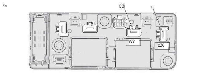
| *a | Component without harness connected
(HV Battery Junction Block Assembly) |
- | - |
- Standard Resistance (SMRB):
Tester Connection Condition Specified Condition W7-1 (CBI) - z26-1 (+) Ignition switch off 10 kΩ or higher
Measure the resistance according to the value(s) in the table below.
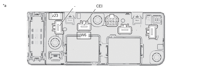
| *a | Component without harness connected
(HV Battery Junction Block Assembly) |
- | - |
- Standard Resistance (SMRG, SMRP):
Tester Connection Condition Specified Condition W6-1 (CEI) - z23-1 (-) Ignition switch off 10 kΩ or higher
Reconnect the high voltage cable connectors to the HV battery junction block assembly.
- Result:
Proceed to OK NG
OK
NG
Turn the ignition switch to ON (READY).
Perform a road test.
- NOTICE:
-
Accelerate/decelerate gently. Avoid rapid acceleration/deceleration.
Drive the vehicle with the value of Data List item "Hybrid/EV Battery Current" between -50 A to 50 A.
- Powertrain > HV Battery > Data List
-
Tester Display Hybrid/EV Battery Current - 50003 398 289
- HINT:
-
Distance and driving time are not specified.
Turn the ignition switch off and leave the vehicle for 30 seconds or more.
Turn the ignition switch to ON.
Check that the value of "Hybrid/EV Battery Current" is between - 0.5 A and 0.5 A with the ignition switch ON.
- Powertrain > HV Battery > Data List
-
Tester Display Hybrid/EV Battery Current - 50003 398 289
- NOTICE:
- ·
If the value is outside the specified range, perform the road test again.
·This DTC may be output if Current Sensor Offset Learning has not been completed.
- HINT:
- ·
If the ignition switch is ON and value of "Hybrid/EV Battery Current" is between - 0.5 A and 0.5 A, current sensor offset learning has been completed.
·Even if the current sensor offset learning is not complete, the current sensor value will be corrected by repeating the road test a maximum of 7 times.
Turn the ignition switch off.
- Result:
Proceed to NEXT
NEXT