HYBRID / BATTERY CONTROL MOTOR GENERATOR CONTROL SYSTEM P0D2D16 Drive Motor "A" Inverter Voltage Sensor(VH) Circuit Voltage Below Threshold P0D2D17 Drive Motor "A" Inverter Voltage Sensor(VH) Circuit Voltage Above Threshold P0D2D1F Drive Motor "A" Inverter Voltage Sensor(VH) Circuit Intermittent
DESCRIPTION
The inverter contains a three-phase bridge circuit, which consists of 6 power transistors (IGBTs) each for the generator (MG1) and motor (MG2). The inverter converts high-voltage direct current from the HV battery into three-phase alternating current for the generator (MG1) and motor (MG2); it also converts three-phase alternating current supplied by generator (MG1) and motor (MG2) into direct current for the HV battery. The motor generator control ECU (MG ECU) controls the actuation of the power transistors (IGBTs). The inverter transmits information necessary for control, such as amperage and voltage, to the motor generator control ECU (MG ECU).
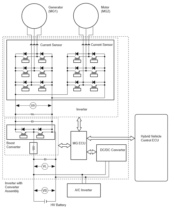
The motor generator control ECU (MG ECU) uses an inverter voltage sensor, which is built into the inverter, to detect boosted high voltage (VH) and allow control of the voltage boost.
The inverter voltage sensor outputs voltage that fluctuates between 0 to 5 V according to changes in VH.
The motor generator ECU monitors the inverter voltage sensor and detects the following malfunctions.
| DTC No. | Detection Item | DTC Detection Condition | Trouble Area | MIL | Warning Indicate | Note |
|---|---|---|---|---|---|---|
| P0D2D16 | Drive Motor "A" Inverter Voltage Sensor(VH) Circuit Voltage Below Threshold | Inverter voltage (VH) signal is stuck low:
DTC stored when the VH sensor signal is excessively low. (1 trip detection logic) |
Inverter with converter assembly | Comes on | Master Warning:
Comes on |
SAE Code:
P0D2F |
| P0D2D17 | Drive Motor "A" Inverter Voltage Sensor(VH) Circuit Voltage Above Threshold | Inverter voltage (VH) signal is stuck high:
DTC stored when the VH sensor signal is excessively high. (1 trip detection logic) |
Inverter with converter assembly | Comes on | Master Warning:
Comes on |
SAE Code:
P0D30 |
| P0D2D1F | Drive Motor "A" Inverter Voltage Sensor(VH) Circuit Intermittent | An excessively high or low voltage signal is output from the inverter voltage sensor (VH) when DTC P0C7917, P0E5717, P0D3319, P1C5D19 or P1C5F19 is stored.
(1 trip detection logic) |
Inverter with converter assembly | Does not come on | Master Warning:
Does not come on |
SAE Code:
P0D31 |
MONITOR DESCRIPTION
The motor generator control ECU monitors the inverter voltage (VH) sensor circuit. If the motor generator control ECU detects an open or short in the VH sensor circuit, the ECU will illuminate the MIL and store a DTC.
MONITOR STRATEGY
| Related DTCs | P0D2F (INF P0D2D16): Drive Motor "A" Inverter Voltage Sensor Range check (Low voltage)
P0D30 (INF P0D2D17): Drive Motor "A" Inverter Voltage Sensor Range check (High voltage) |
| Required sensors/components | Motor inverter voltage sensor |
| Frequency of operation | Continuous |
| Duration | TMC's intellectual property |
| MIL operation | Immediately |
| Sequence of operation | None |
TYPICAL ENABLING CONDITIONS
| The monitor will run whenever the following DTCs are not stored | TMC's intellectual property |
| Other conditions belong to TMC's intellectual property | - |
TYPICAL MALFUNCTION THRESHOLDS
| TMC's intellectual property | - |
COMPONENT OPERATING RANGE
| Motor generator control ECU | DTC P0D2F (INF P0D2D16) is not detected
DTC P0D30 (INF P0D2D17) is not detected |
CONFIRMATION DRIVING PATTERN
- HINT:
- ·
After repair has been completed, clear the DTC and then check that the vehicle has returned to normal by performing the following All Readiness check procedure.
·When clearing the permanent DTCs, refer to the "CLEAR PERMANENT DTC" procedure.
Clear the DTCs (even if no DTCs are stored, perform the clear DTC procedure).
Turn the ignition switch off and wait for 2 minutes or more.
Turn the ignition switch to ON (READY) and wait for 5 seconds or more. [*1]
- HINT:
-
[*1]: Normal judgment procedure.
-
The normal judgment procedure is used to complete DTC judgment and also used when clearing permanent DTCs.
Enter the following menus: Powertrain / Motor Generator / Utility / All Readiness.
Check the DTC judgment result.
- HINT:
- ·
If the judgment result shows NORMAL, the system is normal.
·If the judgment result shows ABNORMAL, the system has a malfunction.
·If the judgment result shows INCOMPLETE, perform the normal judgment procedure again.
PROCEDURE
- Result:
Proceed to NEXT
NEXT