PB10 HYBRID TRANSMISSION / TRANSAXLE SHIFT LEVER POSITION SENSOR INSTALLATION
CAUTION / NOTICE / HINT
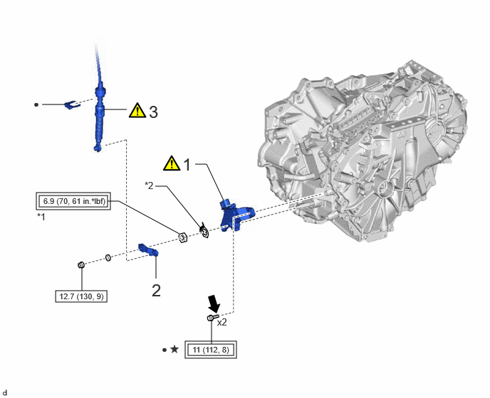
| Procedure | Part Name Code | 
|

|

|
|
|---|---|---|---|---|---|
| 1 | SHIFT LEVER POSITION SENSOR | 89451A | ( 202307,999999,_52,_144756,_0603126,RM100000002BO8J_01_0017,) 202307,999999,_52,_144756,_0603126,RM100000002BO8J_01_0017,)
|
- | - |
| 2 | TRANSMISSION CONTROL SHAFT LEVER | 33572D | - | - | - |
| 3 | TRANSMISSION CONTROL CABLE ASSEMBLY | 33820B | (202307,999999,_52,_144756,_0603126,RM100000002BO8J_01_0002,)
|
- | - |
| *1 | LOCK NUT | *2 | LOCK PLATE |

|
Tightening torque for "Major areas involving basic vehicle performance such as moving/turning/stopping": N*m (kgf*cm, ft.*lbf) | 
|
N*m (kgf*cm, ft.*lbf): Specified torque |
| ● | Non-reusable part | 
|
Toyota Genuine Adhesive 1324, Three Bond 1324 or equivalent |
| ★ | Precoated part | - | - |
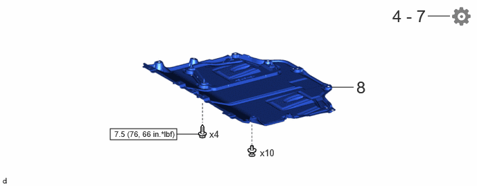
| Procedure | Part Name Code |
|
|
|
|
|---|---|---|---|---|---|
| 4 | INSPECT SHIFT LEVER POSITION SENSOR POSITION | - | - | - | (202307,999999,_52,_144756,_0603126,RM100000002BO8J_01_0008,)
|
| 5 | ADJUST SHIFT LEVER POSITION SENSOR POSITION | - | - | - | (202307,999999,_52,_144756,_0603126,RM100000002BO8J_01_0009,)
|
| 6 | INSPECT SHIFT LEVER POSITION | - | - | - | (202307,999999,_52,_144756,_0603126,RM100000002BO8J_01_0010,)
|
| 7 | ADJUST SHIFT LEVER POSITION | - | - | - | (202307,999999,_52,_144756,_0603126,RM100000002BO8J_01_0011,)
|
| 8 | NO. 1 ENGINE UNDER COVER ASSEMBLY | 51410 | - | - | - |
|
|
N*m (kgf*cm, ft.*lbf): Specified torque | - | - |
PROCEDURE

 89451A
1.INSTALL SHIFT LEVER POSITION SENSOR
89451A
1.INSTALL SHIFT LEVER POSITION SENSOR
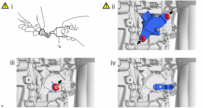
| *a | Adhesive | - | - |
Apply adhesive to 2 new bolts.
- Adhesive:
Toyota Genuine Adhesive 1324, Three Bond 1324 or equivalent
Temporarily install the shift lever position sensor to the hybrid vehicle transaxle assembly with the 2 bolts.
- NOTICE:
- ·
Do not reuse the shift lever position sensor if it has been dropped or subjected to a severe impact.
·Do not allow moisture to adhere to the connector terminal.
Install the lock plate to the shift lever position sensor with the lock nut.
- Torque:
- 6.9 N*m (70 kgf*cm, 61 in.*lbf)
Temporarily install the transmission control shaft lever to the shift lever position sensor.
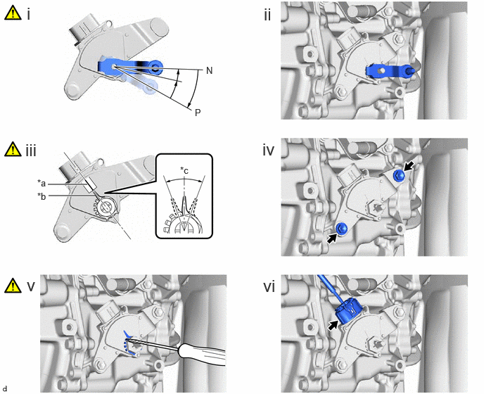
| *a | Neutral Basic Line | *b | Indicator |
| *c | Range of Play | - | - |
Turn the transmission control shaft lever clockwise until it stops, then turn it counterclockwise 2 notches.
Remove the transmission control shaft lever from the shift lever position sensor.
Align the indicator with the neutral basic line.
- NOTICE:
-
The indicator of the lock plate has a certain amount of play. Align the center point of the range of play with the neutral basic line.
Fully tighten the 2 bolts.
- Torque:
- 11 N*m (112 kgf*cm, 8 ft.*lbf)
Using a screwdriver with its tip wrapped with protective tape, secure the lock nut with the lock plate.
Connect the shift lever position sensor connector.
35572D
2.INSTALL TRANSMISSION CONTROL SHAFT LEVER
- Torque:
- 12.7 N*m (130 kgf*cm, 9 ft.*lbf)
33820B
3.CONNECT TRANSMISSION CONTROL CABLE ASSEMBLY
|
|
|
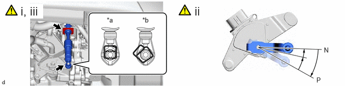
| *a | Correct | *b | Incorrect |
Connect the transmission control cable assembly to the No. 1 transmission control cable bracket with a new clip.
Turn the transmission control shaft lever clockwise until it stops, then turn it counterclockwise 2 notches.
Connect the transmission control cable assembly to the transmission control shaft lever as shown in the illustration.
4.INSPECT SHIFT LEVER POSITION SENSOR POSITION
5.ADJUST SHIFT LEVER POSITION SENSOR POSITION
6.INSPECT SHIFT LEVER POSITION
7.ADJUST SHIFT LEVER POSITION
51410
8.INSTALL NO. 1 ENGINE UNDER COVER ASSEMBLY