NAVIGATION / MULTI INFO DISPLAY NAVIGATION SYSTEM(Production Date from 2023/04) OPERATION CHECK
CHECK NAVIGATION SYSTEM NORMAL CONDITION
If the cause of a symptom is any of the following, the corresponding symptom is normal; it is not due to a malfunction.
| Symptom | Answer |
|---|---|
| A longer route than expected is chosen. | Depending on the road conditions, the radio and display receiver assembly may determine that a longer route is quicker. |
| Even when distance priority is high, the shortest route is not shown. | Some routes may not be advised due to safety concerns. |
| When the vehicle is put into motion immediately after the hybrid system starts, the navigation system deviates from the correct position.*1 | If the vehicle starts before the navigation system activates, the system may not react. |
| When the vehicle is put into motion immediately after the engine starts, the navigation system deviates from the correct position.*2 | |
| When driving on certain types of roads, especially new roads, the vehicle position deviates from the correct position. | When the vehicle is driving on new roads not available on the internal memory, the system attempts to match it to another nearby road, causing the position mark to deviate. |
| Route guidance uses roads with congestion | If the congestion is short, congested road avoidance will not be performed. |
| Some specific areas of the map are not displayed | Urban map areas without data will not be displayed. |
*1: for HEV Model
*2: for Gasoline Model
The following symptoms are not malfunctions, but may occur due to margin of error in the GNSS, gyro sensor, speed sensor or navigation system.
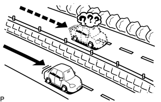
The current position mark may be displayed on a nearby parallel road.
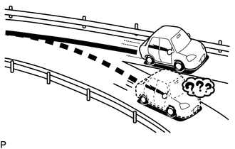
Immediately after a fork in the road, the current vehicle position mark may be displayed on the wrong road.
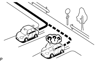
When the vehicle turns right or left at an intersection, the current vehicle position mark may be displayed on a nearby parallel road.
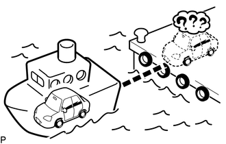
When the vehicle is carried, such as on a ferry, and the vehicle itself is not driving, the current vehicle position mark may be displayed in the position where the vehicle was until a measurement can be performed by the GNSS.
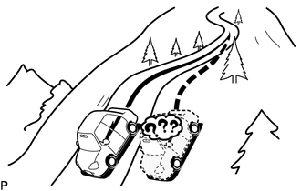
When the vehicle travels on a steep hill, the current vehicle position mark may deviate from the correct position.
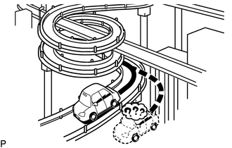
When the vehicle makes a continuous turn (e.g. 360, 720, 1080 degrees), the current vehicle position mark may deviate from the correct position.
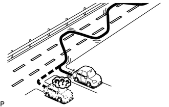
When the vehicle moves erratically, such as constant lane changes, the current vehicle position mark may deviate from the correct position.
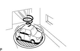
When the ignition switch is turned to ACC or ON and the vehicle is turned on a turntable before parking, the current vehicle position mark may not indicate the correct direction. The same will occur when the vehicle comes out of the parking garage.
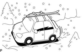
When the vehicle travels on a snowy road or a mountain path with tire chains installed or using a spare tire, the current vehicle position mark may deviate from the correct position.
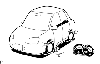
When the tires are changed, the current vehicle position mark may deviate from the correct position.
- HINT:
- ·
A change in tire diameter may cause a speed sensor error.
·Performing "tire change" in calibration mode will allow the system to correct the current vehicle position faster.
CHECK SPEAKER
- HINT:
- ·
For information on how to start diagnosis and transition to each screen, refer toAudio / Visual / Telematics>NAVIGATION / MULTI INFO DISPLAY>NAVIGATION SYSTEM (Production Date from 2023/04)>DIAGNOSIS SYSTEM202201,999999,_56,_111967,_0588532,RM1000000029ZSR,
·This function can check the wire harness between the radio and display receiver assembly and each speaker for malfunctions.
Enter diagnostic mode.
Start diagnosis and display the "Service Menu" screen.
Select "Failure Diagnosis" on the "Service Menu" screen to display the failure diagnosis screen.
Select "System Check" of the failure diagnosis screen to display the system check mode screen.
Speaker check
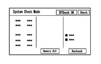
Select "SPCheck ON" from the "System Check Mode" screen.
Check that each speaker outputs sound properly.
- HINT:
- ·
"SPCheck OFF" is displayed during the speaker check.
·Sound can be heard from the speakers around the vehicle in order beginning from the speaker on the front side.
·The sounding order during speaker check cannot be adjusted.
·More than one speaker may sound simultaneously depending on the speaker wiring.
·If sound is not output from a speaker, check the wire harness between the radio and display receiver assembly and each speaker for a malfunction.
Sound stops when any of the following conditions are met:
"SPCheck OFF" is selected.
The screen is changed to another screen.
Diagnostic mode is turned off.
The ignition switch is turned off.
CHECK PANEL SWITCH
- HINT:
-
For enter diagnostic mode and screen transition, refer toAudio / Visual / Telematics>NAVIGATION / MULTI INFO DISPLAY>NAVIGATION SYSTEM (Production Date from 2023/04)>DIAGNOSIS SYSTEM202201,999999,_56,_111967,_0588532,RM1000000029ZSR,
Enter diagnostic mode.
Enter diagnostic mode.
Select "Function Check/Setting" from the "Service Menu" screen.
Select "Panel Switch" on the "Function Check/Setting I" screen to display the "Panel Switch Check Mode" screen.
Panel Switch Check Mode
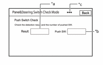
Operate each switch and check that the switch conditions are correctly displayed.
| Display | Content |
|---|---|
| *a: Switch condition | "Pushed" is displayed when any switch is pushed. |
| *b: Name of switch pushed | Name of switch pushed at once is displayed. |
| *c: Communication method | The steering pad switch assembly method of communication is displayed. |
- HINT:
-
If the result of a switch check for the radio and display receiver assembly is abnormal, it can be suspected that the radio and display receiver assembly is malfunctioning.
CHECK TOUCH SWITCH
- HINT:
-
For enter diagnostic mode and screen transition, refer toAudio / Visual / Telematics>NAVIGATION / MULTI INFO DISPLAY>NAVIGATION SYSTEM (Production Date from 2023/04)>DIAGNOSIS SYSTEM202201,999999,_56,_111967,_0588532,RM1000000029ZSR,
Enter diagnostic mode.
Enter diagnostic mode.
Select "Function Check/Setting" from the "Service Menu" screen.
Select "Touch Switch Check" on the "Function Check/Setting I" screen to display the "Touch Switch Check" screen.
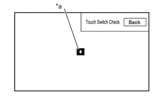
| *a | "+" mark |
Touch Switch Check
Touch the display anywhere in the open area to perform the check when the "Touch Switch Check" screen is displayed.
A "+" mark is displayed where the display is touched.
- HINT:
- ·
The "+" mark remains on the display even after your finger is removed.
·If the result of the touch switch check is abnormal, it can be suspected that the multi-display is malfunctioning.
CHECK MICROPHONE
- HINT:
-
For enter diagnostic mode and screen transition, refer toAudio / Visual / Telematics>NAVIGATION / MULTI INFO DISPLAY>NAVIGATION SYSTEM (Production Date from 2023/04)>DIAGNOSIS SYSTEM202201,999999,_56,_111967,_0588532,RM1000000029ZSR,
Enter diagnostic mode.
Enter diagnostic mode.
Select "Function Check/Setting" from the "Service Menu" screen.
Select "Microphone Check" on the "Function Check/Setting I" screen to display the microphone check screen.
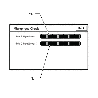
Microphone Check
| Display | Content |
|---|---|
| *a: Microphone 1 input level meter | Displays the input level in 8 steps for microphone 1 |
| *b: Microphone 2 input level meter | Displays the input level in 8 steps for microphone 2 |
Speak to the microphone and check that the microphone input level meter changes according to the input level.
- HINT:
-
The microphone input level is updated every 0.1 seconds.
- OK:
The microphone input level changes
CHECK SYSTEM SENSORS
- HINT:
-
For enter diagnostic mode and screen transition, refer toAudio / Visual / Telematics>NAVIGATION / MULTI INFO DISPLAY>NAVIGATION SYSTEM (Production Date from 2023/04)>DIAGNOSIS SYSTEM202201,999999,_56,_111967,_0588532,RM1000000029ZSR,
Enter diagnostic mode.
Enter diagnostic mode.
Select "Function Check/Setting" from the "Service Menu" screen.
Select "System Sensors Check" on the "Function Check/Setting I" screen to display the "System Sensors Check" screen.
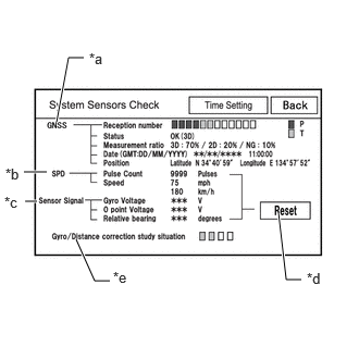
System Sensors Check
| Display | Content | ||
|---|---|---|---|
| Reception number | Displays reception condition of the satellites used to determine vehicle position | Blue: P (In use) | System is using GNSS signal for location. |
| Yellow: T (Receiving) | System is tracking GNSS signal for location. | ||
| No color: Not in use | ·
When "Data collected, unused measurement" notification is received via the GNSS receiver ·
When "searching" notification is received from the GNSS receiver |
||
| Status | Displays reception status of the satellites used to determine vehicle position | OK (3D) | 3-dimensional location method is being used. |
| OK (2D) | 2-dimensional location method is being used. | ||
| NG | Location data cannot be used. | ||
| error | Reception error has occurred. | ||
| - | Any other state. | ||
| Measurement ratio | Displays the ratio of satellites performing measurements | 3D | The ratio of satellites performing 3D positioning is displayed. |
| 2D | The ratio of satellites performing 2D positioning is displayed. | ||
| NG | The ratio of satellites not performing measurement is displayed. | ||
| Date | Date/time information obtained from GNSS signals is displayed in Greenwich Mean Time (GMT). | ||
| Position | Latitude and longitude information on current position is displayed. | ||
| Display | Content | Signal Input Terminal |
|---|---|---|
| Pulse Count | Displays the accumulated number of input pulses beginning when this screen is displayed | Terminal SPD of the radio and display receiver assembly |
| Speed | Displays vehicle speed |
| Display | Content | Note |
|---|---|---|
| Gyro Voltage | Displays the output voltage of the gyro sensor | - |
| 0 point Voltage | Displays the zero-point voltage of the gyro sensor | - |
| Relative bearing | Displays the output angle of the gyro sensor | The amount of change in bearing angle (degrees) after the system sensor check screen is displayed (clockwise: "+", counterclockwise: "-"). |
| Display | Content |
|---|---|
| Reset | When this switch is pressed and held for 3 seconds or more, the values for the display items of SPD signal and gyro sensor signal are reset and display "0". |
| Display | Content |
|---|---|
| Gyro/Distance correction study situation | Displays learning status of Gyro/Distance correction |
- HINT:
- ·
This screen is updated once per second.
·When the vehicle speed calculated from the GNSS signal differs from the SPD signal, DTC B228231 is stored.
·When the output voltage of the gyro sensor is abnormal, DTC B15AD96 is stored.
GNSS TIME SETTING
- HINT:
-
For enter diagnostic mode and screen transition, refer toAudio / Visual / Telematics>NAVIGATION / MULTI INFO DISPLAY>NAVIGATION SYSTEM (Production Date from 2023/04)>DIAGNOSIS SYSTEM202201,999999,_56,_111967,_0588532,RM1000000029ZSR,
Enter diagnostic mode.
Enter diagnostic mode.
Select "Function Check/Setting" from the "Service Menu" screen.
Select "System Sensors Check" from the "Function Check/Setting I" screen.
Select "Time Setting" on the "System Sensors Check" screen to display the GNSS Time Setting screen.
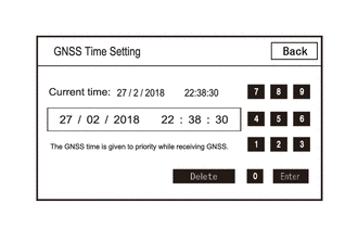
GNSS Time Setting
- HINT:
-
When GNSS radio waves can be received, GNSS time is prioritized.
CHECK VEHICLE SIGNAL
- HINT:
-
For enter diagnostic mode and screen transition, refer toAudio / Visual / Telematics>NAVIGATION / MULTI INFO DISPLAY>NAVIGATION SYSTEM (Production Date from 2023/04)>DIAGNOSIS SYSTEM202201,999999,_56,_111967,_0588532,RM1000000029ZSR,
Enter diagnostic mode.
Enter diagnostic mode.
Select "Function Check/Setting" from the "Service Menu" screen.
Select "Vehicle Signal" on the "Function Check/Setting I" screen to display the Vehicle Signal Check Mode screen.
Vehicle Signal Check Mode
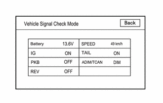
Check the vehicle signal status stored in the radio and display receiver assembly.
| Display | Content | Signal Input Terminal |
|---|---|---|
| Battery | Auxiliary battery voltage is displayed. | Terminal +B1 of the radio and display receiver assembly |
| IG | Ignition switch ON/OFF state is displayed. | Terminal IG of the radio and display receiver assembly |
| PKB | Parking brake ON/OFF state is displayed. | Terminal PKB of the radio and display receiver assembly |
| REV | Reverse signal ON/OFF state is displayed. | Terminal REV of the radio and display receiver assembly |
| SPEED | Vehicle speed is displayed in km/h. | Terminal SPD of the radio and display receiver assembly |
| TAIL | Tail signal (light control switch) ON/OFF state is displayed. | Terminal ILL+ of the radio and display receiver assembly |
| ADIM/TCAN | Brightness state DIM (with) / BRIGHT (without) is displayed. | Input via CAN communication |
- HINT:
- ·
This screen is updated once per second.
·If vehicle signals other than ADIM/TCAN is abnormal, inspect each terminal and wire harness.
·If vehicle signal ADIM/TCAN is abnormal, it can be judged that the CAN communication system is malfunctioning.
for HEV Model: Click herePower Source / Network>NETWORKING>CAN COMMUNICATION SYSTEM (for HEV Model)>HOW TO PROCEED WITH TROUBLESHOOTING202307,999999,_57,_104409,_0606038,RM100000002C0LC,
for Gasoline Model: Click herePower Source / Network>NETWORKING>CAN COMMUNICATION SYSTEM (for Gasoline Model)>HOW TO PROCEED WITH TROUBLESHOOTING202307,202405,_57,_104409,_0605911,RM100000002C07Y,202405,999999,_57,_104409,_0605911,RM100000002NU3H,
CHECK "Bluetooth" COMMUNICATION TRACE OUTPUT
- HINT:
-
For enter diagnostic mode and screen transition, refer toAudio / Visual / Telematics>NAVIGATION / MULTI INFO DISPLAY>NAVIGATION SYSTEM (Production Date from 2023/04)>DIAGNOSIS SYSTEM202201,999999,_56,_111967,_0588532,RM1000000029ZSR,
Connect the USB memory device to the No. 1 stereo jack adapter assembly.
Enter diagnostic mode.
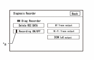
| *a | Green Indicator |
Start diagnosis and display the "Service Menu" screen.
Select "Failure Diagnosis" on the "Service Menu" screen to display the "Failure Diagnosis" screen.
Select "Diagnosis Recorder" on the "Failure Diagnosis" screen to display the "Diagnosis Recorder" screen.
Select "Recording ON/OFF" on the "Diagnosis Recorder" screen to turn off the indicator (green).
Press and hold (for 3 seconds) "BT Trace output" on the "Diagnosis Recorder" screen.
- HINT:
-
When the indicator (green) of "Recording ON/OFF" is illuminated, "BT Trace output" is grayed out and cannot be selected.
BT Trace Output
In accordance with the display, save the "Bluetooth" Connection History recorded data.
Select "Recording ON/OFF" on the "Diagnosis Recorder" screen to turn on the indicator (green).
- HINT:
- ·
When performing the above procedure, make sure to set the indicator (green) of "Recording ON/OFF" back to the illuminated state.
·The Bluetooth Connection History is stored in the ECU internal memory, and consists of timestamped operation data. By checking "Bluetooth" Connection History, the date, cause, etc. of a "Bluetooth" device failing to register or connect can be analyzed.
CHECK "Wi-Fi" COMMUNICATION TRACE OUTPUT
- HINT:
-
For enter diagnostic mode and screen transition, refer toAudio / Visual / Telematics>NAVIGATION / MULTI INFO DISPLAY>NAVIGATION SYSTEM (Production Date from 2023/04)>DIAGNOSIS SYSTEM202201,999999,_56,_111967,_0588532,RM1000000029ZSR,
Connect the USB memory device to the No. 1 stereo jack adapter assembly.
Enter diagnostic mode.
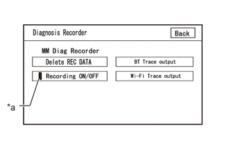
| *a | Green Indicator |
Enter diagnostic mode.
Select "Failure Diagnosis" from the "Service Menu" screen.
Select "Diagnosis Recorder" from the "Failure Diagnosis" screen.
Select "Recording ON/OFF" on the "Diagnosis Recorder" screen and turn off the "Recording ON/OFF" green indicator.
Select "Wi-Fi Trace output" for 3 seconds.
- HINT:
-
When the green "Recording ON/OFF" indicator is illuminated, the "Wi-Fi" Trace output" is grayed out and cannot be selected.
"Wi-Fi" Trace Output
According to the instructions on the screen, save the "Wi-Fi" Connection History data to a USB memory device.
Select "Recording ON/OFF" on the Diagnosis Recorder screen to illuminate the green "Recording ON/OFF" indicator.
- HINT:
- ·
Make sure that the green "Recording ON/OFF" indicator returns to illuminated state, after performing the above procedure.
·This function is used to check the connection history when the connection between the radio and display receiver assembly and a "Wi-Fi" device is unstable.
CHECK NAVIGATION VOICE GUIDANCE SETTING (VOICE GUIDANCE NOT SOUNDING)
Check settings
Set the volume to maximum in the volume setting in the settings screen and inspect the vocalization.
- Standard:
Voice guidance can be heard.
- HINT:
- In the following situations, voice guidance is not performed even if the system is operating normally.·
When a destination has not been set.
·When voice guidance is muted.
CHECK GYRO INTIALIZATION (Vehicle position mark is rotating)
Perform operation again
Turn the ignition switch from off to on (IG), and check if the system returns to normal.
- Standard:
The system returns to normal.
- HINT:
- ·
If the ignition switch is turned to ACC or ON (IG) while the vehicle is being rotated (on a turntable, etc.), the system will display the vehicle position mark as rotating even when there is no malfunction as the radio and display receiver assembly will store the angular velocity as the reference value.
·In the above situation, turn the ignition switch from off to ACC with the vehicle stopped to return the vehicle to normal.