METER / GAUGE / DISPLAY METER / GAUGE SYSTEM Tachometer Malfunction
DESCRIPTION
The combination meter assembly receives engine speed signals from the hybrid vehicle control ECU via CAN communication. The combination meter assembly displays the engine speed calculated based on the data received from the hybrid vehicle control ECU.
The combination meter assembly receives engine speed signals from the ECM via CAN communication. The combination meter assembly displays the engine speed calculated based on the data received from the ECM.
WIRING DIAGRAM

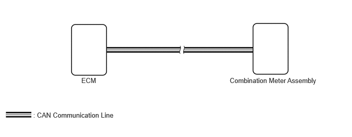
CAUTION / NOTICE / HINT
- NOTICE:
- ·
When replacing the combination meter assembly, always replace it with a new one. If a combination meter assembly which was installed to another vehicle is used, the information stored in it will not match the information from the vehicle and a DTC may be stored.
·Before replacing the ECM, refer to Service Bulletin.
·When replacing the combination meter assembly, update the ECU security key.
- for HEV Model·
When replacing the hybrid vehicle control ECU, update the ECU security key.
·Before replacing the hybrid vehicle control ECU, refer to Service Bulletin.
- for Gasoline Model·
When replacing the ECM, update the ECU security key.
·Before replacing the ECM, refer to Service Bulletin.
PROCEDURE
Choose the model to be inspected.
- Result:
Result Proceed to for HEV Model A for Gasoline Model B
A
B
Check if CAN communication DTCs are output.
- Result:
Result Proceed to DTCs are not output A DTCs are output B
A
B
Check if hybrid control system DTCs are output.
- Powertrain > Hybrid Control > Trouble Codes
- 50001 397
- Result:
Result Proceed to DTCs are not output A DTCs are output B
A
B
Read the Data List according to the display on the GTS.
- Body Electrical > Combination Meter > Data List
-
Tester Display Measurement Item Range Normal Condition Diagnostic Note Engine RPM Engine speed input Min.: 0 rpm, Max.: 12701 rpm or Unset Almost the same as actual tachometer The value displayed on the tachometer may deviate.*
- Body Electrical > Combination Meter > Data List
-
Tester Display Engine RPM - 50003 409 24
- OK:
Engine speed displayed on the GTS is almost the same as the tachometer indication.
- Result:
Result Proceed to The value displayed in the Data List and on the tachometer approximately match A The value displayed in the Data List and on the tachometer do not match B
A
B
Check if CAN communication DTCs are output.
- Result:
Result Proceed to DTCs are not output A DTCs are output B
A
B
Check if SFI system DTCs are output.
- Powertrain > Engine > Trouble Codes
- 50001 372
- Result:
Result Proceed to DTCs are not output A DTCs are output B
A
B
Read the Data List according to the display on the GTS.
- Body Electrical > Combination Meter > Data List
-
Tester Display Measurement Item Range Normal Condition Diagnostic Note Engine RPM Engine speed input Min.: 0 rpm, Max.: 12701 rpm or Unset Almost the same as actual tachometer The value displayed on the tachometer may deviate.*
- Body Electrical > Combination Meter > Data List
-
Tester Display Engine RPM - 50003 409 24
- OK:
Engine speed displayed on the GTS is almost the same as the tachometer indication.
- Result:
Result Proceed to The value displayed in the Data List and on the tachometer approximately match A The value displayed in the Data List and on the tachometer do not match B
A
B