HEATING / AIR CONDITIONING AIR CONDITIONING SYSTEM(for HEV Model) B14744B A/C Inverter Cooling/Heating Over Temperature
DESCRIPTION
The temperature sensor of the compressor with motor assembly detects the A/C inverter temperature.
If the temperature exceeds the maximum, operation of the compressor with motor assembly will be stopped, and this DTC will be stored.
| DTC No. | Detection Item | DTC Detection Condition | Trouble Area | Memory |
|---|---|---|---|---|
| B14744B | A/C Inverter Cooling/Heating Over Temperature | Diagnosis Condition:
READY ON Malfunction Status: A/C inverter temperature outside specified range (temperature too high) Detection Time: None |
·
Cooling fan system ·
Refrigerant volume ·
Compressor with motor assembly |
Memorized |
CAUTION / NOTICE / HINT
- CAUTION:
- ·
Before inspecting the high-voltage system, take safety precautions such as wearing insulated gloves and removing the service plug grip to prevent electrical shocks. After removing the service plug grip, put it in your pocket to prevent other technicians from accidentally reconnecting it while you are working on the high-voltage system.
·Do not touch the high-voltage connectors or terminals for 10 minutes after the service plug grip is removed.
- NOTICE:
- ·
After turning the ignition switch off, waiting time may be required before disconnecting the cable from the negative (-) auxiliary battery terminal. Therefore, make sure to read the disconnecting the cable from the negative (-) auxiliary battery terminal notices before proceeding with work.
·When the cable is disconnected from the negative (-) auxiliary battery terminal, the memory of various systems will be cleared. Because of this, be sure to make a record of the contents memorized in each system before starting work. When work is finished, adjust each system to its previous state.
·The hybrid control system and air conditioning system output DTCs separately. Perform troubleshooting for the hybrid control system first if DTCs for both systems are output simultaneously.
·The air conditioning system uses the CAN communication system. Inspect the communication functions by following How to Proceed with Troubleshooting. Troubleshoot the air conditioning system after confirming that the communication systems are functioning properly.
PROCEDURE
Perform the Active Test according to the display on the GTS.
- Powertrain > Engine > Active Test
-
Tester Display Measurement Item Control Range Diagnostic Note Control the Engine Cooling Fan Control the cooling fan OFF / Low / High -
- Powertrain > Engine > Active Test
-
Tester Display Control the Engine Cooling Fan - 50004 372 26
- OK:
Cooling fan operates smoothly.
- Result:
Proceed to OK NG
OK
NG
Install a manifold gauge set.
Prepare the vehicle according to the table below.
| Item | Condition |
|---|---|
| Vehicle doors | Fully open |
| Temperature setting | MAX COLD |
| Blower speed | HI |
| A/C switch | On |
| Recirculation/fresh switch | RECIRCULATION |
| Interior temperature | 25 to 35°C (77 to 95°F) |
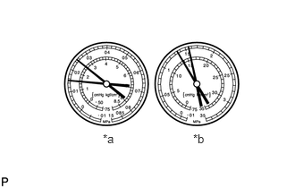
| *a | LO |
| *b | HI |
Read the manifold gauge pressure when the following conditions are met.
- Standard Pressure:
- Low pressure side:
150 to 250 kPa (1.5 to 2.5 kgf/cm2, 22 to 36 psi)
- High pressure side:
1370 to 1570 kPa (14 to 16 kgf/cm2, 199 to 228 psi)
- HINT:
-
The standard pressure is applicable when the refrigerant gas is filled to the correct amount.
- Result:
Proceed to OK NG
OK
NG
Clear the DTCs.
- Body Electrical > Air Conditioner > Clear DTCs
- 50002 450
- Result:
Proceed to NEXT
NEXT
Set the vehicle so that the conditions for detecting DTCs are met.
Put the vehicle in Inspection Mode (engine forced to idle).
- HINT:
Prepare the vehicle according to the table below for 30 minutes.
| Item | Condition |
|---|---|
| Blower speed | HI |
| A/C switch | On |
| Temperature setting | MAX COLD |
Check for DTCs.
- Body Electrical > Air Conditioner > Trouble Codes
- 50001 450
- NOTICE:
-
If the engine idles continuously when ambient temperature is high, the compressor with motor assembly may automatically stop to protect the inverter circuit, and DTC B14744B may be stored.
- Result:
Result Proceed to B14744B is not output A B14744B is output B
A
B