HEATING / AIR CONDITIONING AIR CONDITIONING SYSTEM(for HEV Model) Operation not Accepted Even If Air Conditioning Switch is Operated
DESCRIPTION
If the air conditioning system cannot be operated using the air conditioning control assembly, the following factors may be the cause.
| Symptom | Factor |
|---|---|
| Air conditioning system cannot be operated using air conditioning control assembly
(With the exception of the switch indicators, no inputs are reflected when other switches operated) |
·
LIN communication malfunction between air conditioning amplifier assembly and air conditioning control assembly ·
Short to +B or ground in air conditioning amplifier assembly circuit ·
Air conditioning amplifier assembly malfunction ·
Air conditioning control assembly malfunction ·
Harness or connector |
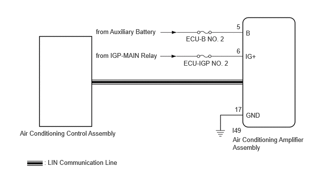
WIRING DIAGRAM
CAUTION / NOTICE / HINT
- NOTICE:
-
Inspect the fuses for circuits related to this system before performing the following procedure.
PROCEDURE
Check for DTCs.
- Body Electrical > Air Conditioner > Trouble Codes
- 50001 450
- Result:
Result Proceed to B14B287 is not output A B14B287 is output B
A
B
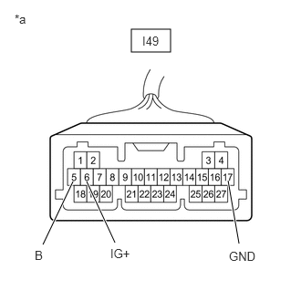
| *a | Front view of wire harness connector
(to Air Conditioning Amplifier Assembly) |
Disconnect the I49 air conditioning amplifier assembly connector.
Measure the voltage and resistance according to the value(s) in the table below.
- Standard Voltage:
Tester Connection Switch Condition Specified Condition I49-5 (B) - Body ground Ignition switch off 11 to 14 V I49-6 (IG+) - Body ground Ignition switch ON 11 to 14 V Ignition switch off Below 1 V
- Standard Resistance:
Tester Connection Condition Specified Condition I49-17 (GND) - Body ground Always Below 1 Ω
- Result:
Proceed to OK NG
OK
NG