HEATING / AIR CONDITIONING AIR CONDITIONING SYSTEM(for HEV Model) B14B287 Lost Communication with Front Panel LIN Missing Message
DESCRIPTION
The air conditioning control assembly communicates with the air conditioning amplifier assembly via LIN communication.
If a malfunction occurs in the LIN communication system, the air conditioning amplifier assembly will not operate, even if the air conditioning control assembly is operated.
| DTC No. | Detection Item | DTC Detection Condition | Trouble Area | Memory |
|---|---|---|---|---|
| B14B287 | Lost Communication with Front Panel LIN Missing Message | Diagnosis Condition:
Ignition switch ON Malfunction Status: Error or lost communication with air conditioning control assembly Detection Time: Continuously for 10 seconds or more |
·
Air conditioning control assembly ·
Harness or connector ·
Air conditioning amplifier assembly |
Memorized |
| Vehicle Condition | |||
|---|---|---|---|
| Pattern 1 | Pattern 2 | ||
| Diagnosis Condition | Ignition switch ON | ○ | ○ |
| Malfunction | Error communication with air conditioning control assembly | ○ | - |
| Lost communication with air conditioning control assembly | - | ○ | |
| Detection Time | Continuously for 10 seconds or more | Continuously for 10 seconds or more | |
| Trip Count | 1 trip | 1 trip | |
- HINT:
-
If the conditions of either of these patterns are detected, a DTC will be stored.
WIRING DIAGRAM
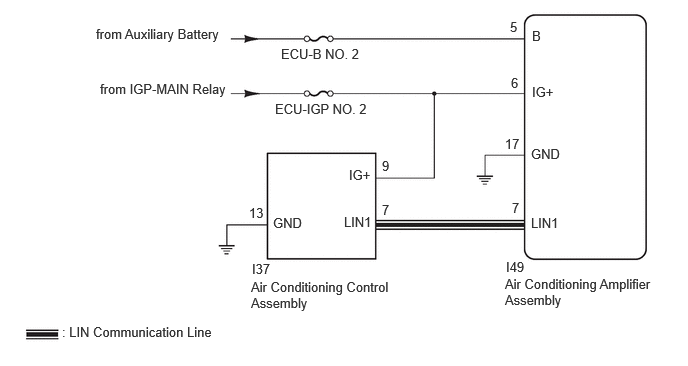
CAUTION / NOTICE / HINT
- NOTICE:
-
Inspect the fuses for circuits related to this system before performing the following procedure.
PROCEDURE
Disconnect the I37 air conditioning control assembly connector.
Measure the voltage according to the value(s) in the table below.
- Standard Voltage:
Tester Connection Switch Condition Specified Condition I37-9 (IG+) - Body ground Ignition switch ON 11 to 14 V I37-9 (IG+) - Body ground Ignition switch off Below 1 V
- Result:
Proceed to OK NG
OK
NG
Measure the resistance according to the value(s) in the table below.
- Standard Resistance:
Tester Connection Condition Specified Condition I37-13 (GND) - Body ground Always Below 1 Ω
- Result:
Proceed to OK NG
OK
NG
Disconnect the I49 air conditioning amplifier assembly connector.
Measure the resistance according to the value(s) in the table below.
- Standard Resistance:
Tester Connection Condition Specified Condition I37-7 (LIN1) - I49-7 (LIN1) Always Below 1 Ω I37-7 (LIN1) or I49-7 (LIN1) - Other terminals and body ground Always 10 kΩ or higher
- Result:
Proceed to OK NG
OK
NG
Using an oscilloscope, check the waveform.
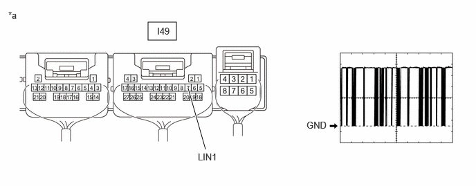
| *a | Component with harness connected
(Air Conditioning Amplifier Assembly) |
- | - |
| Tester Connection | Tool Setting | Switch Condition |
|---|---|---|
| I49-7 (LIN1) - Body ground | 2 V/DIV., 20 ms./DIV. | Ignition switch ON |
- OK:
Waveform is similar to that shown in the illustration.
- Result:
Proceed to OK NG
OK
NG