SLIDING ROOF / CONVERTIBLE SLIDING ROOF SYSTEM(Production Date from 2023/04) B234149 Sliding Roof Motor Internal Electronic Failure B234407 Sliding Roof Position Mechanical Failure
DESCRIPTION
When the sliding roof ECU (sliding roof drive gear sub-assembly) detects a motor malfunction and the sliding roof operation is stopped, DTC B234149 is stored.
When the sliding roof ECU (sliding roof drive gear sub-assembly) detects a gear position malfunction and the sliding roof operation is stopped, DTC B234407 is stored.
| DTC No. | Detection Item | DTC Detection Condition | Trouble Area | DTC Output from |
|---|---|---|---|---|
| B234149 | Sliding Roof Motor Internal Electronic Failure | Sensor (motor) failure (The sliding roof ECU (sliding roof drive gear sub-assembly) enters fail-safe mode due to a problem with the motor) | ·
Sliding roof ECU (sliding roof drive gear sub-assembly) ·
Sliding roof switch (Map light assembly) ·
Wire harness or connector |
Main Body |
| B234407 | Sliding Roof Position Mechanical Failure | Position failure (The sliding roof ECU (sliding roof drive gear sub-assembly) enters fail-safe mode due to a problem with the gear position) | ·
Sliding roof ECU (sliding roof drive gear sub-assembly) ·
Sliding roof switch (Map light assembly) ·
Wire harness or connector |
Main Body |
WIRING DIAGRAM
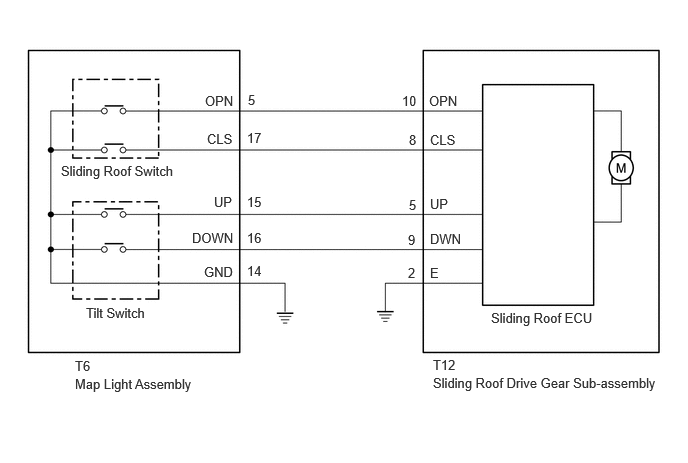
CAUTION / NOTICE / HINT
- NOTICE:
-
If the sliding roof ECU (sliding roof drive gear sub-assembly) is removed and reinstalled or replaced, the sliding roof ECU (sliding roof drive gear sub-assembly) must be initialized.
PROCEDURE
Check the sliding roof auto operation.
- OK:
Auto operation operates normally.
- Result:
Proceed to OK NG
OK
NG
Clear the DTCs.
- Body Electrical > Main Body > Clear DTCs
- 50002 449
Check for DTCs.
- Body Electrical > Main Body > Trouble Codes
- 50001 449
- Result:
Result Proceed to DTCs are not output A DTCs are output B
A
B
Check that the sliding roof ECU (sliding roof drive gear sub-assembly) can be initialized.
- OK:
Sliding roof ECU (sliding roof drive gear sub-assembly) can be initialized.
- Result:
Proceed to OK NG
OK
NG
Clear the DTCs.
- Body Electrical > Main Body > Clear DTCs
- 50002 449
Check for DTCs.
- Body Electrical > Main Body > Trouble Codes
- 50001 449
- Result:
Result Proceed to DTCs are not output A DTCs are output B
A
B
Disconnect the T6 sliding roof switch (map light assembly) connector.
Disconnect the T12 sliding roof ECU (sliding roof drive gear sub-assembly) connector.
Measure the resistance according to the value(s) in the table below.
- Standard Resistance:
Tester Connection Condition Specified Condition T12-8 (CLS) - T6-17 (CLS) Always Below 1 Ω T12-8 (CLS) or T6-17 (CLS) - Body ground Always 10 kΩ or higher T12-10 (OPN) - T6-5 (OPN) Always Below 1 Ω T12-10 (OPN) or T6-5 (OPN) - Body ground Always 10 kΩ or higher T12-9 (DWN) - T6-16 (DOWN) Always Below 1 Ω T12-9 (DWN) or T6-16 (DOWN) - Body ground Always 10 kΩ or higher T12-5 (UP) - T6-15 (UP) Always Below 1 Ω T12-5 (UP) or T6-15 (UP) - Body ground Always 10 kΩ or higher T6-14 (GND) - Body ground Always Below 1 Ω T12-2 (E) - Body ground Always Below 1 Ω
- Result:
Proceed to OK NG
OK
NG
- Result:
Proceed to OK NG
OK
NG