LIGHTING (INT) LIGHTING SYSTEM TERMINALS OF ECU
CHECK MAIN BODY ECU (MULTIPLEX NETWORK BODY ECU) AND POWER DISTRIBUTION BOX ASSEMBLY
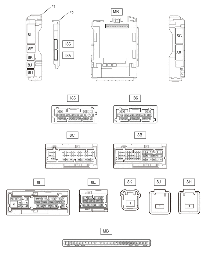
| *1 | Power Distribution Box Assembly | *2 | Main body ECU (multiplex network body ECU) |
Remove the main body ECU (multiplex network body ECU) from the power distribution box assembly.
Connect the power distribution box assembly connectors.
Measure the voltage and resistance according to the value(s) in the table below.
| Terminal No. (Symbol) | Terminal Description | Condition | Specified Condition |
|---|---|---|---|
| MB-13 (GND1) - Body ground | Ground | Always | Below 1 Ω |
| MB-14 (GND2) - Body ground | Ground | Always | Below 1 Ω |
| MB-26 (BECU) - Body ground | Auxiliary battery power supply | Ignition switch off | 11 to 14 V |
| MB-27 (IGR) - Body ground | Ignition power supply | Ignition switch off | Below 1 V |
| Ignition switch ON | 11 to 14 V |
Install the main body ECU (multiplex network body ECU).
Connect the power distribution box assembly and main body ECU (multiplex network body ECU) connectors.
Measure the voltage and check for pulses according to the value(s) in the table below.
| Terminal No. (Symbol) | Terminal Description | Condition | Specified Condition |
|---|---|---|---|
| 8F-3 - Body ground | Front door courtesy light switch (LH) signal | Front door LH open | Below 1 V |
| Front door LH closed | 11 to 14 V, or Pulse Output (Maximum 14 V)*1 | ||
| 8C-9 - Body ground | Front door courtesy light switch (RH) signal | Front door RH open | Below 1 V |
| Front door RH closed | 11 to 14 V, or Pulse Output (Maximum 14 V)*1 | ||
| 8F-28 - Body ground | Rear door courtesy light switch (LH) signal | Rear door LH open | Below 1 V |
| Rear door LH closed | 11 to 14 V, or Pulse Output (Maximum 14 V)*1 | ||
| 8F-1 - Body ground | Rear door courtesy light switch (RH) signal | Rear door RH open | Below 1 V |
| Rear door RH closed | 11 to 14 V, or Pulse Output (Maximum 14 V)*1 | ||
| 8F-18 - Body ground | No. 1 luggage compartment light assembly ground | No. 1 luggage compartment light assembly off | 11 to 14 V |
| No. 1 luggage compartment light assembly on | Below 1 V | ||
| 8F-20 - Body ground | No. 1 luggage compartment light assembly power supply | DOME CUT relay off | 11 to 14 V |
| DOME CUT relay on | Below 1 V | ||
| 8C-2 - Body ground | Each instrument panel illumination power supply | Light control switch in neither tail nor head position | Below 1 V |
| Light control switch in tail or head position | 11 to 14 V | ||
| 8C-4 - Body ground | Interior light power supply | DOME CUT relay off | 11 to 14 V |
| DOME CUT relay on | Below 1 V | ||
| I85-5 (ILE) - Body ground | Illuminated entry system drive output | Illuminated entry system inactive | 11 to 14 V |
| Illuminated entry system operation | Below 1 V | ||
| 8F-9 - Body ground | Multiplex network master switch assembly illumination light power supply | Multiplex network master switch assembly illumination light off | Below 1 V |
| Multiplex network master switch assembly illumination light on | 11 to 14 V | ||
| 8F-2 - Body ground | Back door courtesy light switch signal | Back door closed | 11 to 14 V, or Pulse Output (Maximum 14 V)*1 |
| Back door open | Below 1 V | ||
| I85-9 (LSFL) - Body ground | Front door LH unlock detection switch input | Front door LH locked | 11 to 14 V, or Pulse Output (Maximum 14 V)*1 |
| Front door LH unlocked | Below 1 V | ||
| I85-3 (LSFR) - Body ground | Front door RH unlock detection switch input | Front door RH locked | 11 to 14 V, or Pulse Output (Maximum 14 V)*1 |
| Front door RH unlocked | Below 1 V | ||
| I85-10 (LSWL) - Body ground | Rear door LH unlock detection switch input | Rear door LH locked | 11 to 14 V, or Pulse Output (Maximum 14 V)*1 |
| Rear door LH unlocked | Below 1 V | ||
| I86-23 (LSWR) - Body ground | Rear door RH unlock detection switch input | Rear door RH locked | 11 to 14 V, or Pulse Output (Maximum 14 V)*1 |
| Rear door RH unlocked | Below 1 V |
*1: Differs depending on the vehicle model
- NOTICE:
-
*: If the low beam headlights or clearance lights illuminate when the ignition switch is turned ON, shine a light on the automatic light control sensor to turn the low beam headlights off before operating the headlight dimmer switch.
CHECK CERTIFICATION ECU (SMART KEY ECU ASSEMBLY) (w/ Smart Entry and Start System)
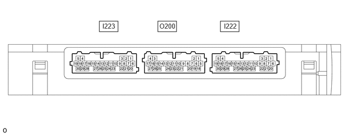
Measure the voltage according to the value(s) in the table below.
| Terminal No. (Symbol) | Terminal Description | Condition | Specified Condition |
|---|---|---|---|
| I222-20 (SWIL) - I222-30 (AGND) | Push start switch illumination drive output | Push start switch illumination off | Below 1 V |
| Push start switch illumination on | 11 to 14 V |