RM38T0EC
_58
Vehicle Interior
_115226
DOOR LOCK
_0510938
KEY REMINDER WARNING SYSTEM
U
DOOR LOCK KEY REMINDER WARNING SYSTEM TERMINALS OF ECU
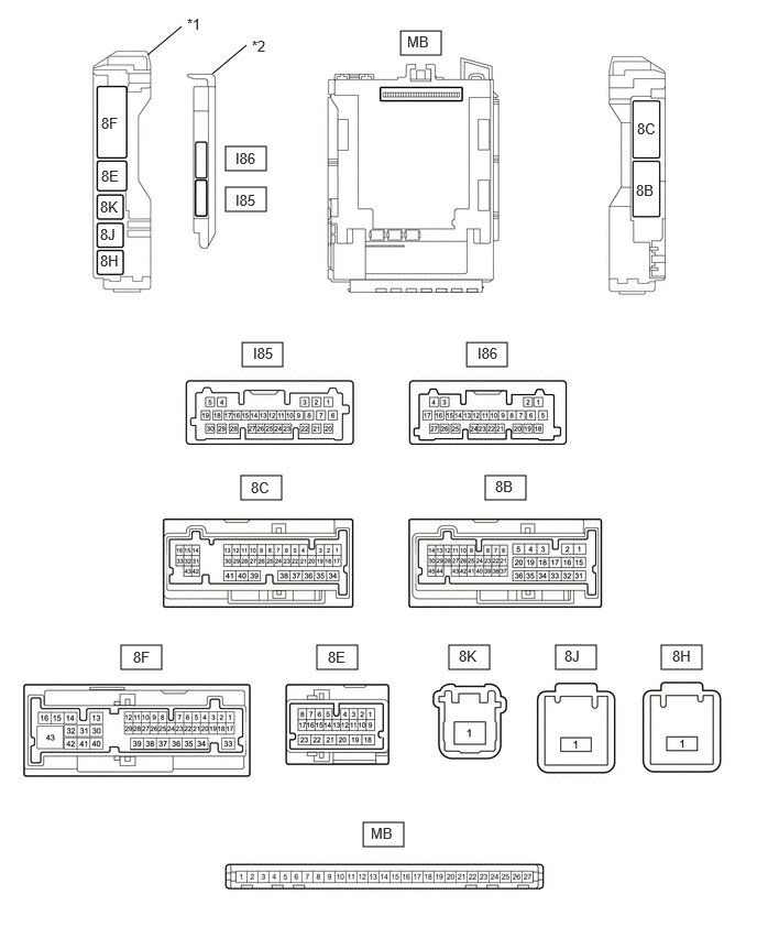
CHECK MAIN BODY ECU (MULTIPLEX NETWORK BODY ECU) AND POWER DISTRIBUTION BOX ASSEMBLY
4.417,3.24 4.802,3.469
0.385,0.229
2.281,4.5 2.667,4.729
0.385,0.229
4.594,4.5 4.979,4.729
0.385,0.229
1.146,6.104 1.531,6.333
0.385,0.229
3,6.104 3.385,6.333
0.385,0.229
4.25,6.104 4.635,6.333
0.385,0.229
3.438,7.781 3.823,8.01
0.385,0.229
2.135,1.385 2.521,1.615
0.385,0.229
2.135,1.771 2.521,2
0.385,0.229
2.292,3.24 2.677,3.469
0.385,0.229
3.792,0.292 4.177,0.521
0.385,0.229
5.26,6.104 5.646,6.333
0.385,0.229
6.26,6.104 6.646,6.333
0.385,0.229
2.01,0.698 2.333,0.427
false
1.396,0.521 1.719,0.25
false
0.948,1.875 1.26,2.073
0.313,0.198
10
false
8K
0.948,2.385 1.26,2.583
0.313,0.198
10
false
8H
0.958,1.083 1.271,1.281
0.313,0.198
10
false
8F
0.958,1.583 1.271,1.781
0.313,0.198
10
false
8E
2.229,1.417 2.688,1.615
0.458,0.198
10
false
I86
2.229,1.813 2.688,2.01
0.458,0.198
10
false
I85
3.854,0.313 4.24,0.5
0.385,0.188
10
false
MB
2.396,3.26 2.865,3.469
0.469,0.208
10
false
I85
4.521,3.26 4.979,3.458
0.458,0.198
10
false
I86
3.104,6.135 3.563,6.333
0.458,0.198
10
false
8E
3.51,7.802 3.969,8
0.458,0.198
10
false
MB
2.385,0.354 2.698,0.552
0.313,0.198
10
false
*2
6.021,1.719 6.333,1.917
0.313,0.198
10
false
8B
6.031,1.135 6.344,1.333
0.313,0.198
10
false
8C
0.948,2.135 1.26,2.333
0.313,0.198
10
false
8J
4.688,4.521 5,4.719
0.313,0.198
10
false
8B
2.375,4.531 2.688,4.729
0.313,0.198
10
false
8C
1.26,6.135 1.573,6.333
0.313,0.198
10
false
8F
4.344,6.125 4.656,6.323
0.313,0.198
10
false
8K
5.344,6.125 5.656,6.323
0.313,0.198
10
false
8J
6.365,6.125 6.677,6.323
0.313,0.198
10
false
8H
1.771,0.146 2.083,0.344
0.313,0.198
10
false
*1
| *1 | Power Distribution Box Assembly | *2 | Main body ECU (multiplex network body ECU) |
a.
Remove the main body ECU (multiplex network body ECU) from the power distribution box assembly.
b.
Reconnect the power distribution box assembly connector.
c.
Measure the voltage and resistance according to the value(s) in the table below.
- HINT:
-
Measure the values on the wire harness side with the connectors connected.
| Terminal No. (Symbol) | Terminal Description | Condition | Specified Condition |
|---|---|---|---|
| MB-13 (GND1) - Body ground | Ground | Always | Below 1 Ω |
| MB-14 (GND2) - Body ground | Ground | Always | Below 1 Ω |
| MB-26 (BECU) - Body ground | Auxiliary battery power supply | Ignition switch off | 11 to 14 V |
| MB-27 (IGR) - Body ground | IG power supply | Ignition switch ON | 11 to 14 V |
d.
Install the main body ECU (multiplex network body ECU) to power distribution box assembly.
e.
Measure the voltage and check for pulses according to the value(s) in the table below.
| Terminal No. (Symbol) | Terminal Description | Condition | Specified Condition |
|---|---|---|---|
| 8F-3 (FLCY) - Body ground | Front door courtesy light switch (LH) input | Front door LH open | Below 1 V |
| Front door LH closed | 11 to 14 V | ||
| I85-16 (KSW) - Body ground | Un-lock warning switch input | No key in ignition key cylinder | 11 to 14 V |
| Key in ignition key cylinder | Below 1 V |