POWER ASSIST SYSTEMS POWER STEERING SYSTEM C151A17 Power Steering Torque Sensor "A" Supply Voltage Circuit Voltage Above Threshold
DESCRIPTION
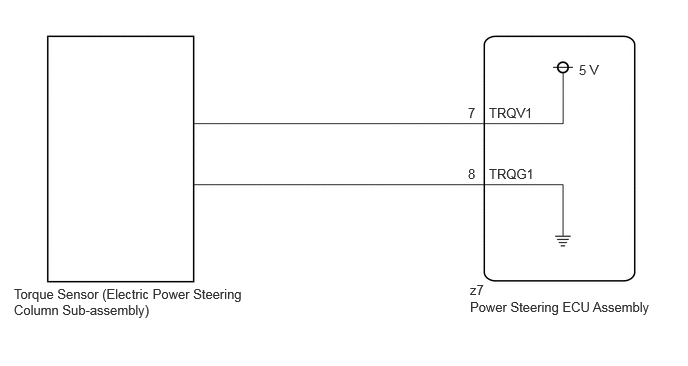
The power steering ECU assembly supplies a voltage of 5 V to the torque sensor (electric power steering column sub-assembly) and monitors the voltage value of the Hall IC inside the torque sensor (electric power steering column sub-assembly) which changes in response to changes in the magnetic flux density (steering torque) detected by the Hall IC, and calculates the assist torque.
While DTC C151A17 is detected, power assist is stopped or assist amount is limited due to fail-safe operation.
| DTC No. | Detection Item | DTC Detection Condition | Trouble Area | Warning Indicate |
|---|---|---|---|---|
| C151A17 | Power Steering Torque Sensor "A" Supply Voltage Circuit Voltage Above Threshold | TRQV1 voltage is high voltage abnormality | ·
Torque sensor (Electric power steering column sub-assembly) ·
Power steering ECU assembly |
EPS warning light: Comes on |
WIRING DIAGRAM
CAUTION / NOTICE / HINT
- NOTICE:
- ·
When the electric power steering column sub-assembly has been replaced, perform Power Steering ECU Initial Setting (assist map writing).
·When the power steering ECU assembly has been replaced, perform Power Steering ECU Initial Setting (assist map writing).
PROCEDURE
Disconnect the z7 power steering ECU assembly connector.
Measure the resistance according to the value(s) in the table below.
- Standard Resistance:
Tester Connection Condition Specified Condition z7-7 (TRQV1) - Body ground Always 10 kΩ or higher z7-7 (TRQV1) - z7-8 (TRQG1) Always 10 kΩ or higher
- Result:
Proceed to OK NG
OK
NG
Start the engine.
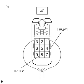
| *a | Component with harness connected
(Power Steering ECU Assembly) |
Measure the voltage according to the value(s) in the table below.
- Standard Voltage:
Tester Connection Switch Condition Specified Condition z7-7 (TRQV1) - z7-8 (TRQG1) Ignition switch ON 4.5 to 5.5 V
- Result:
Proceed to OK NG
OK
NG