WINDOW / GLASS WINDOW DEFOGGER SYSTEM TERMINALS OF ECU
CHECK POWER DISTRIBUTION BOX ASSEMBLY AND MAIN BODY ECU (MULTIPLEX NETWORK BODY ECU)
Remove the main body ECU (multiplex network body ECU).
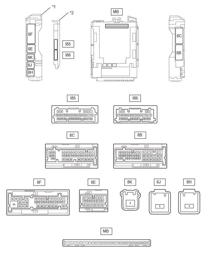
| *1 | Power Distribution Box Assembly | *2 | Main Body ECU (Multiplex Network Body ECU) |
Reconnect the power distribution box assembly connectors.
Measure the voltage and resistance according to the value(s) in the table below.
| Terminal No. (Symbol) | Terminal Description | Condition | Specified Condition |
|---|---|---|---|
| MB-13 (GND1) - Body ground | Ground | Always | Below 1 Ω |
| MB-14 (GND2) - Body ground | Ground | Always | Below 1 Ω |
| MB-26 (BECU) - Body ground | Auxiliary battery power supply | Ignition switch off | 11 to 14 V |
| MB-27 (IGR) - Body ground | IG power supply | Ignition switch off | Below 1 V |
| Ignition switch ON | 11 to 14 V |
Install the main body ECU (multiplex network body ECU).
Measure the voltage and check for pulses according to the value(s) in the table below.
| Terminal No. (Symbol) | Terminal Description | Condition | Specified Condition |
|---|---|---|---|
| 8C-23 - Body ground*1 | Rear window defogger signal (input) | Rear window defogger switch off | Below 1 V |
| Rear window defogger switch on | 11 to 14 V | ||
| 8F-43 - Body ground | Rear window defogger signal (output) | Rear window defogger switch off | Below 1 V |
| Rear window defogger switch on | 11 to 14 V |
*1: for Mechanical Control Type
CHECK AIR CONDITIONING AMPLIFIER ASSEMBLY (for Electrical Control Type)
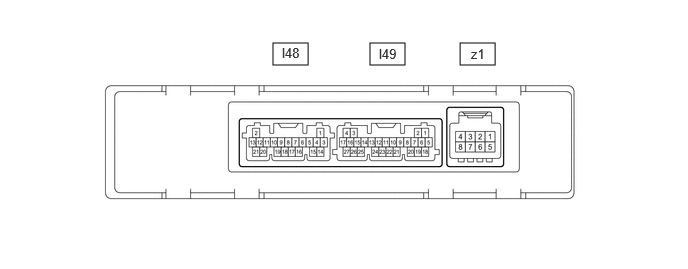
Disconnect the I49 air conditioning amplifier assembly connector.
Measure the voltage and resistance according to the value(s) in the table below.
- HINT:
-
Measure the values on the wire harness side with the connector disconnected.
| Terminal No. (Symbol) | Terminal Description | Condition | Specified Condition |
|---|---|---|---|
| I49-6 (IG+) - I49-17 (GND) | Power source (IG) | Ignition switch ON | 11 to 14 V |
| Ignition switch off | Below 1 V | ||
| I49-17 (GND) - Body ground | Ground for main power supply | Always | Below 1 Ω |
Reconnect the I49 air conditioning amplifier assembly connector.
Check for pulses according to the value(s) in the table below.
| Terminal No. (Symbol) | Terminal Description | Condition | Specified Condition |
|---|---|---|---|
| I49-1 (CANL) - I49-2 (CANH) | CAN communication system | CAN communication is performed | Pulse generation |
| I49-7 (LIN1) - I49-17 (GND) | LIN communication line | Ignition switch ON | Pulse generation |
CHECK AIR CONDITIONING CONTROL ASSEMBLY (for Electrical Control Type)

Disconnect the I37 air conditioning control assembly connector.
Measure the voltage and resistance according to the value(s) in the table below.
- HINT:
-
Measure the values on the wire harness side with the connector disconnected.
| Terminal No. (Symbol) | Terminal Description | Condition | Specified Condition |
|---|---|---|---|
| I37-9 (IG+) - I37-13 (GND) | Power source (IG) | Ignition switch ON | 10.5 to 16 V |
| Ignition switch off | Below 1 V | ||
| I37-13 (GND) - Body ground | Ground | Always | Below 1 Ω |
Reconnect the I37 air conditioning control assembly connector.
Check for pulses according to the value(s) in the table below.
| Terminal No. (Symbol) | Terminal Description | Condition | Specified Condition |
|---|---|---|---|
| I37-7 (LIN1) - I37-13 (GND) | LIN communication line | Ignition switch ON | Pulse generation |