CRUISE CONTROL DYNAMIC RADAR CRUISE CONTROL SYSTEM(for Gasoline Model) P057162 Brake Switch "A" Signal Compare Failure
DESCRIPTION
When the brake pedal is depressed, the stop light switch assembly outputs a signal to the ECM. The ECM uses this signal to control cancellation of vehicle speed by the dynamic radar cruise control. When the ECM determines that terminals STP and ST1- of the stop light switch assembly are both less than 1 V, DTC P057162 is stored.
| DTC No. | Detection Item | DTC Detection Condition | Trouble Area | DTC Output from |
|---|---|---|---|---|
| P057162 | Brake Switch "A" Signal Compare Failure | When the ignition switch is ON and the dynamic radar cruise control system is operating, the ECM detects that the voltage at terminal STP and ST1- are both less than 1 V for approximately 0.5 seconds or more. | ·
Harness or connector ·
Stop light switch assembly ·
ECM |
Cruise Control |
WIRING DIAGRAM
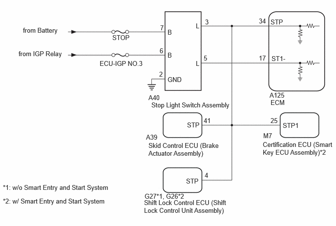
CAUTION / NOTICE / HINT
- NOTICE:
- ·
Inspect the fuses for circuits related to this system before performing the following procedure.
·Before replacing the ECM, refer to the Service Bulletin.
PROCEDURE
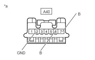
| *a | Front view of wire harness connector
(to Stop Light Switch Assembly) |
Disconnect the stop light switch assembly connector.
Measure the resistance according to the value(s) in the table below.
- Standard Resistance:
Tester Connection Condition Specified Condition A40-2 (GND) - Body ground Always Below 1 Ω
Measure the voltage according to the value(s) in the table below.
- Standard Voltage:
Tester Connection Condition Specified Condition A40-7 (B) - Body ground Always 11 to 14 V A40-6 (B) - Body ground Ignition switch ON 11 to 14 V A40-6 (B) - Body ground Ignition switch off Below 1 V
Connect the stop light switch assembly connector.
- Result:
Proceed to OK NG
OK
NG
Inspect the stop light switch assembly.
- Result:
Proceed to OK NG
OK
NG
Disconnect the A125 ECM connector.
Disconnect the A40 stop light switch assembly connector.
Disconnect the A39 skid control ECU (brake actuator assembly) connector.
w/ Smart Entry and Start System:
Disconnect the M7 certification ECU (smart key ECU assembly) connector.
w/o Smart Entry and Start System:
Disconnect the G27 shift lock control ECU (shift lock control unit assembly) connector.
w/ Smart Entry and Start System:
Disconnect the G26 shift lock control ECU (shift lock control unit assembly) connector.
Measure the resistance according to the value(s) in the table below.
- Standard Resistance:
Tester Connection Condition Specified Condition A125-17 (ST1-) - A40-5 (L) Always Below 1 Ω A125-34 (STP) - A40-3 (L) Always Below 1 Ω A125-17 (ST1-) or A40-5 (L) - Body ground Always 10 kΩ or higher A125-34 (STP) or A40-3 (L) - Body ground Always 10 kΩ or higher
w/ Smart Entry and Start System:
Connect the G26 shift lock control ECU (shift lock control unit assembly) connector.
w/o Smart Entry and Start System:
Connect the G27 shift lock control ECU (shift lock control unit assembly) connector.
w/ Smart Entry and Start System:
Connect the M7 certification ECU (smart key ECU assembly) connector.
Connect the A39 skid control ECU (brake actuator assembly) connector.
Connect the A40 stop light switch assembly connector.
Connect the A125 ECM connector.
- Result:
Proceed to OK NG
OK
for M20C-FKS:
for M20D-FKS:
NG