FRONT SUSPENSION FRONT LOWER BALL JOINT REMOVAL
CAUTION / NOTICE / HINT
The necessary procedures (adjustment, calibration, initialization, or registration) that must be performed after parts are removed and installed, or replaced during front lower ball joint assembly removal/installation are shown below.
| Replaced Part or Performed Procedure | Necessary Procedure | Effect/Inoperative Function when Necessary Procedure not Performed | Link |
|---|---|---|---|
| Front wheel alignment adjustment | 1.
Perform "Reset Memory" 2.
Perform "Calibration" |
·
DTCs are stored ·
ABS warning light illuminates ·
Brake warning light / yellow (minor malfunction) illuminates ·
Slip indicator light illuminates ·
Electronically controlled brake system disabled or malfunctions |
( 202304,999999,_54,_083077,_0401811,RM1000000029TH7,) 202304,999999,_54,_083077,_0401811,RM1000000029TH7,)
|
- HINT:
- for HV Model:
-
When the cable is disconnected / reconnected to the auxiliary battery terminal, systems temporarily stop operating. However, each system has a function that completes learning the first time the system is used.
- ·
Learning completes when vehicle is driven
Effect/Inoperative Function When Necessary Procedures are not Performed Necessary Procedures Link Lane tracing assist system Drive the vehicle straight ahead at 35 km/h (22 mph) or more for 5 second or more. ( 201910,999999,_58,_083101,_0401880,RM100000001JE9I,)
Pre-collision system
·Learning completes when vehicle is operated normally
Effect/Inoperative Function When Necessary Procedures are not Performed Necessary Procedures Link Power back door function Fully close the back door by hand.
- HINT:
-
Initialization is not necessary if the above procedures are performed while the back door is closed.
( 202304,999999,_59,_083093,_0584672,RM1000000029PGT,)
Power door lock control system If the back door is locked and therefore cannot be opened, it is necessary to unlock the back door using the door control switch, electrical key transmitter sub-assembly switch. ( 202409,999999,_58,_083092,_0403003,RM100000002NS90,)
Air conditioning system After the ignition switch is turned to ON, the servo motor standard position is recognized -
·Use the same procedure for the RH and LH sides.
·The following procedure is for the LH side.
| Replaced Part or Performed Procedure | Necessary Procedure | Effect/Inoperative Function when Necessary Procedure not Performed | Link |
|---|---|---|---|
| Front wheel alignment adjustment | 1.
Perform "Reset Memory" 2.
Perform acceleration sensor zero point calibration and store system information memorization |
·
VSC is disabled or malfunctions ·
DTCs are output ·
Slip indicator light illuminates ·
ABS warning light illuminates |
(202304,999999,_54,_083077,_0402316,RM100000002AG8P,)
|
- HINT:
- for Gasoline Model:
- ·
Use the same procedure for the RH and LH sides.
·The following procedure is for the LH side.
PROCEDURE

 1.REMOVE FRONT AXLE ASSEMBLY
43340A
2.REMOVE FRONT LOWER BALL JOINT ASSEMBLY (for Steel Steering Knuckle)
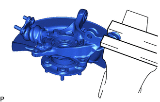
Secure the front axle assembly in a vise using aluminum plates.
- NOTICE:
-
Do not overtighten the vise.
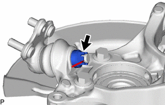
Remove the cotter pin.
Remove the nut.
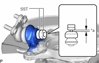
| *a | 1 mm (0.0394 in.) |
Install SST to the front lower ball joint assembly as shown in the illustration.
- SST
- 09960-20010 (09961-02050)
- NOTICE:
-
Check that the clearance measurement between SST and the front axle assembly is 1 mm (0.0394 in.).
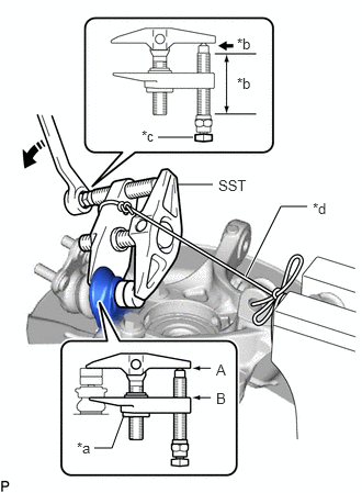
| *a | Center Nut |
| *b | Molybdenum Grease Application Area |
| *c | Place wrench here |
| *d | String |

|
Turn |
Using SST, remove the front lower ball joint assembly from the front axle assembly as shown in the illustration.
- SST
- 09960-20010 (09961-02010, 09961-02050)
- CAUTION:
-
Apply molybdenum grease to the threads and end of the SST bolt.
- NOTICE:
- ·
Be sure to tighten the string firmly to secure SST to the front axle assembly to prevent SST from falling off.
·Install SST with the center nut so that (A) and (B) shown in the illustration are parallel. Otherwise, the front lower ball joint dust cover may be damaged.
·Be sure to place a wrench on the part shown in the illustration.
·Do not damage the front lower ball joint dust cover.
·Do not damage the steering knuckle.
·Do not damage the front disc brake dust cover.
43340A
3.REMOVE FRONT LOWER BALL JOINT ASSEMBLY (for Aluminum Steering Knuckle)
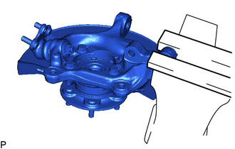
Secure the front axle assembly in a vise using aluminum plates.
- NOTICE:
-
Do not overtighten the vise.
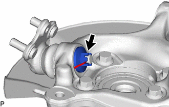
Remove the cotter pin.
Remove the nut.
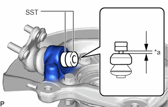
| *a | 1 mm (0.0394 in.) |
Install SST to the front lower ball joint assembly as shown in the illustration.
- SST
- 09960-20010 (09961-02050)
- NOTICE:
- ·
Make sure to install the spacers (SST) as the steering knuckle spacer may shift.
·Check that the clearance measurement between SST and the front axle assembly is 1 mm (0.0394 in.).
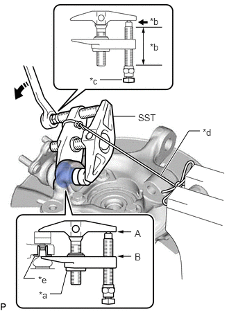
| *a | Center Nut |
| *b | Molybdenum Grease Application Area |
| *c | Place wrench here |
| *d | String |
| *e | Spacer |
|
|
Turn |
Using SST, remove the front lower ball joint assembly from the front axle assembly as shown in the illustration.
- SST
- 09960-20010 (09961-02010, 09961-02050)
- CAUTION:
-
Apply molybdenum grease to the threads and end of the SST bolt.
- NOTICE:
- ·
Be sure to tighten the string firmly to secure SST to the front axle assembly to prevent SST from falling off.
·Install SST with the center nut so that (A) and (B) shown in the illustration are parallel. Otherwise, the front lower ball joint dust cover may be damaged.
·Be sure to place a wrench on the part shown in the illustration.
·Do not damage the front lower ball joint dust cover.
·Do not damage the steering knuckle.
·Do not damage the front disc brake dust cover.
·Make sure that SST is securely positioned on the spacer.
- HINT:
- ·
If the steering knuckle spacer has come off, replace the steering knuckle with a new one.