AXLE AND DIFFERENTIAL REAR AXLE HUB REMOVAL
CAUTION / NOTICE / HINT
The necessary procedures (adjustment, calibration, initialization, or registration) that must be performed after parts are removed and installed, or replaced during rear axle hub removal/installation are shown below.
- HINT:
- ·
When the cable is disconnected / reconnected to the auxiliary battery terminal, systems temporarily stop operating. However, each system has a function that completes learning the first time the system is used. (for HV Model)
-Learning completes when vehicle is driven
Effect/Inoperative Function When Necessary Procedures are not Performed Necessary Procedures Link Lane tracing assist system Drive the vehicle straight ahead at 35 km/h (22 mph) or more for 5 second or more. (  201910,999999,_58,_083101,_0401880,RM100000001JE9I,)
Pre-collision system
-Learning completes when vehicle is operated normally
Effect/Inoperative Function When Necessary Procedures are not Performed Necessary Procedures Link Power back door function Fully close the back door by hand.
- HINT:
-
Initialization is not necessary if the above procedures are performed while the back door is closed.
( 202304,999999,_59,_083093,_0584672,RM1000000029PGT,)
Power door lock control system If the back door is locked and therefore cannot be opened, it is necessary to unlock the back door using the door control switch, electrical key transmitter sub-assembly switch. ( 202409,999999,_58,_083092,_0403003,RM100000002NS90,)
Air conditioning system After the ignition switch is turned to ON, the servo motor standard position is recognized -
·Use the same procedure for the RH and LH sides.
·The following procedure is for the LH side.
PROCEDURE

 1. PRECAUTION (for HV Model)
- NOTICE:
-
After the ignition switch is turned off, there may be a waiting time before disconnecting the negative (-) auxiliary battery terminal.
2.RELEASE PARKING BRAKE
3.DISABLE BRAKE CONTROL (for HV Model)
4.REMOVE REAR WHEEL
890C0A
5.DISCONNECT NO. 2 PARKING BRAKE WIRE ASSEMBLY
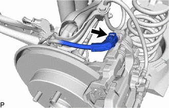
Disconnect the No. 2 parking brake wire assembly connector from the parking brake actuator assembly.
- NOTICE:
- ·
Remove any dirt or foreign matter on and around the No. 2 parking brake wire assembly connector before performing this step.
·Do not allow water, oil or dirt to enter the No. 2 parking brake wire assembly connector.
42312B
6.REMOVE REAR AXLE SHAFT NUT LH (for AWD)
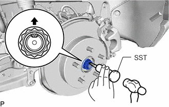
Using SST and a hammer, release the staked part of the rear axle shaft nut LH.
- SST
- 09930-00010
- NOTICE:
-
Loosen the staked part of the rear axle shaft nut LH completely, otherwise the threads of the rear drive shaft assembly may be damaged.
While applying the brakes, remove the rear axle shaft nut LH.
47319F
7.DISCONNECT REAR FLEXIBLE HOSE
8.DISCONNECT REAR DISC BRAKE CALIPER ASSEMBLY LH
42431
9.REMOVE REAR DISC
890C0A
10.DISCONNECT NO. 2 PARKING BRAKE WIRE ASSEMBLY (for 2WD)
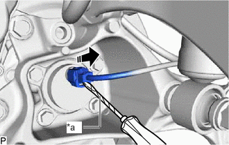
| *a | Protective Tape |
Using a screwdriver with its tip wrapped in protective tape, disconnect the No. 2 parking brake wire assembly connector from the rear axle hub and bearing assembly.
- NOTICE:
-
Be careful not to damage the rear axle hub and bearing assembly and connector cover.
89544E
11.DISCONNECT REAR SKID CONTROL SENSOR LH (for AWD)
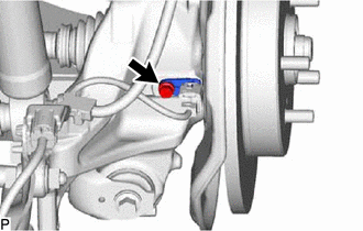
Remove the bolt and disconnect the rear skid control sensor LH from the rear axle carrier sub-assembly.
- NOTICE:
- ·
Keep the tip of the rear skid control sensor LH and installation hole free of foreign matter.
·Do not rotate or apply excessive force to the rear skid control sensor LH when removing it from the rear axle carrier sub-assembly. Rotating or applying excessive force may result in damage to the rear skid control sensor LH.
42450B
12.REMOVE REAR AXLE HUB AND BEARING ASSEMBLY LH (for 2WD)
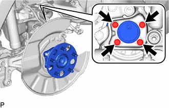
Remove the 4 bolts, rear axle hub and bearing assembly and rear disc brake dust cover sub-assembly from the rear axle carrier sub-assembly.
42450B
13.REMOVE REAR AXLE HUB AND BEARING ASSEMBLY LH (for AWD)
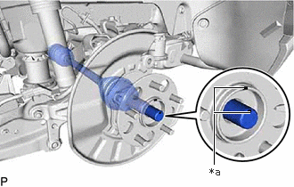
| *a | Matchmark |
Place matchmarks on the rear drive shaft assembly and the rear axle hub and bearing assembly.
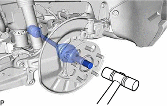
Using a plastic hammer, separate the rear drive shaft assembly from the rear axle hub and bearing assembly.
- NOTICE:
- ·
Do not damage the rear drive shaft outboard joint boot.
·Do not push the rear axle hub and bearing assembly towards the outside of the vehicle any further than necessary.
- HINT:
-
If it is difficult to separate the rear drive shaft assembly rear axle hub and bearing assembly, tap the end of the rear drive shaft assembly using a brass bar and a hammer.
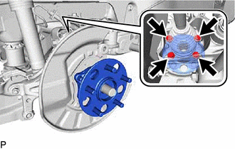
Remove the 4 bolts, rear axle hub and bearing assembly and rear disc brake dust cover sub-assembly from the rear axle carrier sub-assembly.