DOOR / HATCH FUEL LID OPENER SYSTEM TERMINALS OF ECU
CHECK ECM
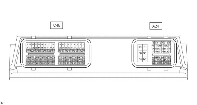
- HINT:
-
The standard voltage, resistance and waveform between each pair of the ECM terminals are shown in the table below. The appropriate conditions for checking each pair of the terminals is also indicated. The result of checks should be compared with the standard voltage, resistance and waveform for each pair of the terminals as displayed in the Specified Condition column. The illustration above can be used as a reference to identify the ECM terminal locations.
| Terminal No. (Symbol) | Wiring Color | Terminal Description | Condition | Specified Condition |
|---|---|---|---|---|
| A24-31 (LIDO) - A24-10 (E1) | GR - W-B | Fuel lid with motor lock assembly (fuel lid courtesy switch) signal | Fuel lid closed | Below 1 V |
| Fuel lid open | 11 to 14 V | |||
| A24-38 (FUEL) - A24-10 (E1) | G - W-B | Fuel lid opener switch signal | Fuel lid opener switch pressed | Below 1 V |
| Fuel lid opener switch not pressed | 4.5 to 5.5 V | |||
| A24-41 (LSTM) - A24-10 (E1) | L - W-B | Fuel lid operation signal for combination meter assembly | "Refuel Ready" displayed on multi-information display | Pulse generation
(see waveform 1) |
| "Close Fuel Lid" displayed on multi-information display | Pulse generation
(see waveform 2) |
|||
| "Please Wait Now Opening" displayed on multi-information display | Pulse generation
(see waveform 3) |
|||
| Power switch on (IG) | 11 to 14 V | |||
| A24-44 (FREL) - A24-10 (E1) | Y - W-B | Fuel lid with motor lock assembly operation signal | Fuel lid with motor lock assembly operating | Below 1 V |
| Fuel lid with motor lock assembly not operating | 11 to 14 V |
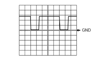
Using an oscilloscope, check waveform 1.
| Item | Content |
|---|---|
| Terminal No. (Symbol) | A24-41 (LSTM) - A24-10 (E1) |
| Tool Setting | 5 V/DIV., 20 ms./DIV. |
| Condition | "Refuel Ready" displayed on multi-information display |
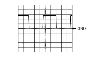
Using an oscilloscope, check waveform 2.
| Item | Content |
|---|---|
| Terminal No. (Symbol) | A24-41 (LSTM) - A24-10 (E1) |
| Tool Setting | 5 V/DIV., 20 ms./DIV. |
| Condition | "Close Fuel Lid" displayed on multi-information display |
- HINT:
-
This waveform is output when the fuel lid opener switch is operated if the fuel lid is open and any of the following conditions are met:
- ·
The vehicle has been driven for 1 km (0.6 mile) or more at a speed of 50 km/h (31 mph) or more.
·30 minutes or more have elapsed since the fuel lid opener switch was operated.
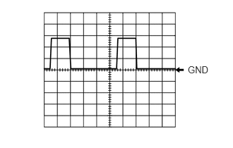
Using an oscilloscope, check waveform 3.
| Item | Content |
|---|---|
| Terminal No. (Symbol) | A24-41 (LSTM) - A24-10 (E1) |
| Tool Setting | 5 V/DIV., 20 ms./DIV. |
| Condition | "Please Wait Now Opening" displayed on multi-information display |
- HINT:
-
This waveform is output when the internal pressure of the fuel tank is higher than the ambient pressure when the fuel lid opener switch is operated.
CHECK COMBINATION METER ASSEMBLY
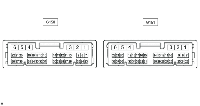
Disconnect the G151 combination meter assembly connector.
Measure the voltage and resistance according to the value(s) in the table below.
| Terminal No. | Wiring Color | Terminal Description | Condition | Specified Condition |
|---|---|---|---|---|
| G151-1 (EP) - Body ground | W-B - Body ground | Ground | Always | Below 1 Ω |
| G151-2 (ES) - Body ground | W-B - Body ground | Ground | Always | Below 1 Ω |
| G151-5 (B) - Body ground | B - Body ground | Auxiliary battery | Power switch off | 11 to 14 V |
| G151-6 (IG+) - Body ground | L - Body ground | Power switch signal | Power switch off | Below 1 V |
| Power switch on (IG) | 11 to 14 V |
Reconnect the G151 combination meter assembly connector.
Measure the waveform and voltage according to the value(s) in the table below.
| Terminal No. (Symbol) | Wiring Color | Terminal Description | Condition | Specified Condition |
|---|---|---|---|---|
|
*1: for SFTM Made *2: for GTMC Made |
||||
| G151-28 (LST1) - Body ground | V - Body ground*1
P - Body ground*2 |
Fuel lid operation signal for combination meter assembly | "Ready to Refuel" displayed on multi-information display | Pulse generation
(see waveform 1) |
| "Close Fuel Lid" displayed on multi-information display | Pulse generation
(see waveform 2) |
|||
| "Please Wait Fuel Door Opening" displayed on multi-information display | Pulse generation
(see waveform 3) |
|||
Using an oscilloscope, check waveform 1.
| Item | Content |
|---|---|
| Terminal No. (Symbol) | G151-28 (LST1) - Body ground |
| Tool Setting | 5 V/DIV., 20 ms./DIV. |
| Condition | "Ready to Refuel" displayed on multi-information display |
Using an oscilloscope, check waveform 2.
| Item | Content |
|---|---|
| Terminal No. (Symbol) | G151-28 (LST1) - Body ground |
| Tool Setting | 5 V/DIV., 20 ms./DIV. |
| Condition | "Close Fuel Lid" displayed on multi-information display |
- HINT:
-
This waveform is output when the fuel lid opener switch is operated if the fuel lid is open and any of the following conditions are met:
- ·
The vehicle has been driven for 1 km (0.6 mile) or more at a speed of 50 km/h (31 mph) or more.
·30 minutes or more have elapsed since the fuel lid opener switch was operated.
Using an oscilloscope, check waveform 3.
| Item | Content |
|---|---|
| Terminal No. (Symbol) | G151-28 (LST1) - Body ground |
| Tool Setting | 5 V/DIV., 20 ms./DIV. |
| Condition | "Please Wait Fuel Door Opening" displayed on multi-information display |
- HINT:
-
This waveform is output when the internal pressure of the fuel tank is higher than the ambient pressure when the fuel lid opener switch is operated.