THEFT DETERRENT / KEYLESS ENTRY SMART ENTRY AND START SYSTEM(for Start Function, Gasoline Model) DATA LIST / ACTIVE TEST
DATA LIST
- NOTICE:
-
In the table below, the values listed under "Normal Condition" are reference values. Do not depend solely on these reference values when deciding whether a part is faulty or not.
- HINT:
-
Using the GTS to read the Data List allows the values or states of switches, sensors, actuators and other items to be read without removing any parts. This non-intrusive inspection can be very useful because intermittent conditions or signals may be discovered before parts or wiring is disturbed. Reading the Data List information early in troubleshooting is one way to save diagnostic time.
Connect the GTS to the DLC3.
Turn the ignition switch to ON.
Turn the GTS on.
Enter the following menus: Body Electrical / (desired system) / Data List.
Read the Data List according to the display on the GTS.
- Body Electrical > Power Source Control > Data List
-
Tester Display Measurement Item Range Normal Condition Diagnostic Note Total Distance Traveled Total distance traveled Min.: 0
Max.: 999999Actual total distance displayed - Total Distance Traveled - Unit Total distance traveled unit km or mile - - Push Start Switch 1 Engine switch 1 status OFF or ON OFF: Engine switch not pressed
ON: Engine switch pressed·If the engine switch is pressed for a short time, the display may not change.
·Use this item to determine if the engine switch input signal is malfunctioning.
Push Start Switch 2 Engine switch 2 status OFF or ON OFF: Engine switch not pressed
ON: Engine switch pressed·If the engine switch is pressed for a short time, the display may not change.
·Use this item to determine if the engine switch input signal is malfunctioning.
Push Start Switch 3 Engine switch 3 status OFF or ON OFF: Engine switch not pressed
ON: Engine switch pressed·If the engine switch is pressed for a short time, the display may not change.
·Use this item to determine if the engine switch input signal is malfunctioning.
Steering Unlock Switch State of steering unlock sensor signal output from steering lock ECU (steering lock actuator with ECU assembly) OFF or ON OFF: Steering locked
ON: Steering unlockedAlthough the item is displayed on the GTS, it is not applicable to this vehicle. Shift P Signal Shift position P OFF or ON OFF: Shift lever not in P
ON: Shift lever in P·Use this item to determine if the shift position switch is malfunctioning.
·The engine cannot be started when this item is OFF.
Stop Light Switch State of brake pedal OFF or ON OFF: Brake pedal released
ON: Brake pedal depressed·Use this item to determine if the stop light switch assembly is malfunctioning.
·The engine cannot be started when this item is OFF.
·If the stop light switch assembly is malfunctioning, the engine can be started by pressing and holding the engine switch for a certain period of time.
Neutral Switch / Clutch Switch - - - Although the item is displayed on the GTS, it is not applicable to this vehicle. Engine Speed Engine speed 0 to 16383.75 rpm Fluctuates in accordance with actual engine speed - IGP Relay Circuit (Outside) Monitor IGP relay coil voltage monitor status OFF or ON OFF: Ignition switch off
ON: Ignition switch ON·Use this item to determine if the IGP relay is malfunctioning.
·When the ignition switch is ACC, OFF is displayed.
IGP Relay Circuit (Inside) Monitor IGP relay activation OFF or ON OFF: Ignition switch off
ON: Ignition switch ON·Use this item to determine if the IGP relay is malfunctioning.
·When the ignition switch is ACC, OFF is displayed.
IGR Relay Circuit (Outside) Monitor IGR relay coil voltage monitor status OFF or ON OFF: Ignition switch off
ON: Ignition switch ON·Use this item to determine if the IGR relay is malfunctioning.
·When the ignition switch is ACC, OFF is displayed.
IGR Relay Circuit (Inside) Monitor IGR relay activation OFF or ON OFF: Ignition switch off
ON: Ignition switch ON·Use this item to determine if the IGR relay is malfunctioning.
·When the ignition switch is ACC, OFF is displayed.
IGP Hold Circuit Monitor IGP relay hold monitor status OFF or ON OFF: Ignition switch off
ON: Ignition switch ON- ACC Relay Monitor ACC relay activation OFF or ON OFF: Ignition switch off
ON: Ignition switch ACCWhen the ignition switch is ON, ON is displayed. IGB Relay Monitor - - - Although the item is displayed on the GTS, it is not applicable to this vehicle. Engine Driving Condition (Line) Engine state Stop or Driving Stop: Engine stopped
Driving: Engine running- Vehicle Running Condition (Line) Vehicle being driven or stopped Stop or Running Stop: Vehicle stopped
Running: Vehicle being driven at 5 km/h (3 mph) or more- IGB Output Condition - - - Although the item is displayed on the GTS, it is not applicable to this vehicle. IGBD Condition - - - Although the item is displayed on the GTS, it is not applicable to this vehicle. Power Supply Condition Power supply state OFF, ACC ON, IGR ON, IGP ON or Starter ON OFF: Ignition switch off
ACC ON: Ignition switch ACC
IGR ON: Ignition switch ON
IGP ON: Ignition switch ON
Starter ON: Sending engine start request signal- Shift P Signal Condition (Line) - - - Although the item is displayed on the GTS, it is not applicable to this vehicle. Powertrain Type Vehicle identification Cnv-MT, Cnv-AT, Cnv-MMT, S&S-MT, S&S-AT, S&S-MMT, HV/FCHV-AT, PHV/EV-AT or 1Motor HV-AT Cnv-AT: Conventional A/T model
S&S-AT: Conventional A/T model with stop and start system- Shift P Signal Mismatch P position signal malfunction Not Detected or Detected Not Detected: Signal normal
Detected: Signal malfunction (signals via CAN communication and direct line do not match)Even when Detected is displayed, it is still possible to turn the ignition switch off (the power source mode will not be stuck in ACC or ON). Steering Lock - Unlock Time Out Steering lock or unlock malfunction Not Detected or Detected Not Detected: Lock and unlock normal
Detected: Lock or unlock malfunction (e.g. steering lock is stuck etc.)Although the item is displayed on the GTS, it is not applicable to this vehicle. Key Certification Time Out Key verification malfunction Not Detected or Detected Not Detected: Verification normal
Detected: Verification error (Detected due to the electrical key transmitter sub-assembly ID code and the ID code stored in the certification ECU (smart key ECU assembly) not matching)When the engine cannot be started due to a key verification error, Yes is displayed. IGR Relay Circuit (Outside) Malfunction IGR relay coil circuit malfunction Not Detected or Detected Not Detected: Circuit normal
Detected: Circuit malfunctioning·Use this item to determine if the IGR relay is malfunctioning.
·When the engine cannot be started due to an IGR relay malfunction, NG is displayed.
IGP Relay Circuit (Outside) Malfunction IGP relay coil circuit malfunction Not Detected or Detected Not Detected: Circuit normal
Detected: Circuit malfunctioning·Use this item to determine if the IGP relay is malfunctioning.
·When the engine cannot be started due to an IGP relay malfunction, NG is displayed.
Starter Relay Driving Request (Starting Control) Engine start request signal status OFF or ON OFF: The engine switch is not pressed
ON: With the shift position in P and the brake pedal depressed, the engine switch is pressed and held·When the engine cannot be started due to a start request signal malfunction, OFF is displayed.
·When the engine switch is pressed, the duration of time that ON is displayed will be extremely short. As such, the engine switch needs to be pressed and held for a certain period of time.
Starter Relay Starter relay voltage monitor OFF or ON OFF: ST relay off
ON: ST relay onWhen OFF is displayed the engine cannot be cranked. Shift P/N (Starting Control) - - - Although the item is displayed on the GTS, it is not applicable to this vehicle. Auto Power OFF Cancel Mode - - - ·Not applicable
·Although the item is displayed on the GTS, it is not applicable to this vehicle.
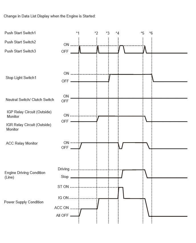
- HINT:
- To check if the Data List display changes, get into the vehicle while carrying an electrical key transmitter sub-assembly and perform the following operations with the ignition switch off and the shift position in P.
- ·
*1: Press the engine switch with the brake pedal released and check that the ignition switch turns ACC.
·*2: Press the engine switch with the brake pedal released and check that the ignition switch turns ON.
·*3: Depress the brake pedal (stop light switch assembly is on).
·*4: Press the engine switch with the brake pedal depressed and check that the engine starts.
·*5: Press the engine switch with the brake pedal depressed and check that the ignition switch turns off.
·*6: Release the brake pedal.
- Body Electrical > Entry&Start > Data List
-
Tester Display Measurement Item Range Normal Condition Diagnostic Note Cut Fuse Cut fuse installed OFF or ON OFF: Cut fuse not installed
ON: Cut fuse installed- Electronic Key No Response Communication response No or Yes No: Communication normal
Yes: Communication malfunctionIf there is wave interference in the LF band that the vehicle uses for transmission or the RF band that the electrical key transmitter sub-assembly uses for transmission, "Yes" may be displayed for "Electronic Key No Response" in the Data List.)
Other potential causes:
·An electrical key transmitter sub-assembly from a different vehicle is being used.
·The electrical key transmitter sub-assembly or certification ECU (smart key ECU assembly) is malfunctioning.
Key Low Battery Transmitter battery depleted No or Yes No: Transmitter battery not depleted
Yes: Transmitter battery depletedThe electrical key transmitter sub-assembly sends voltage information to the certification ECU (smart key ECU assembly) when it is transmitting. "Yes" is displayed for the Data List item "Key Low Battery" when this voltage information indicates 2.2 V or less. This Data List item should be checked when the electrical key transmitter sub-assembly is at room temperature (example: at -20°C (-4°F), "Yes" may be displayed even if the transmitter battery is new). B Code Difference B code mismatch No or Yes No: Communication normal
Yes: Communication malfunction- B Code Registered B code registration status No or Yes No: B code not registered correctly
Yes: B code registered correctly- Immobiliser Immobiliser system status determined by certification ECU (smart key ECU assembly)*5 Set or Unset Set: Immobiliser set (engine start prohibited) (ignition switch off)
Unset: Immobiliser unset (engine start permitted) (ignition switch ACC or ON)The engine cannot be started when Set is displayed.
- HINT:
- ·
The security indicator light blinks when Set is displayed.
·The security indicator light is linked with set/unset of the immobiliser.
Immobiliser when IG=ON Immobiliser function status when ignition switch ON Unset or Set Unset: Immobiliser function not set with ignition switch ON or immobiliser function unset 40 times after immobiliser function set
Set: Immobiliser function set (driver door opened and closed with ignition switch ON)- Master Key Matching of master key ID code and ID code registered in certification ECU (smart key ECU assembly) No or Yes No: ID code of master key does not match ID code registered in certification ECU (smart key ECU assembly)
Yes: ID code of master key matches ID code registered in certification ECU (smart key ECU assembly)- Sub Key Matching of sub key ID code and ID code registered in certification ECU (smart key ECU assembly) No or Yes No: ID code of sub key does not match ID code registered in certification ECU (smart key ECU assembly)
Yes: ID code of sub key matches ID code registered in certification ECU (smart key ECU assembly)- BCC Malfunction BCC signal status of transponder chip*1 No or Yes No: BCC signal malfunction (malfunction in code computation in electrical key transmitter sub-assembly/certification ECU (smart key ECU assembly))
Yes: BCC signal normalProblems may be caused by the following:
·Communication errors due to wave interference (LF).
·The electrical key transmitter sub-assembly or certification ECU (smart key ECU assembly) malfunctioning.
Abnormal Status Transponder chip status signal*1 No or Yes No: Transponder chip status signal normal
Yes: Transponder chip status signal malfunction (malfunction in code computation in electrical key transmitter sub-assembly/certification ECU (smart key ECU assembly))Problems may be caused by the following:
·Communication errors due to wave interference (LF).
·The electrical key transmitter sub-assembly or certification ECU (smart key ECU assembly) malfunctioning.
Encrypt Code Difference Matching of transponder chip code and certification ECU (smart key ECU assembly) code*1 No or Yes No: Codes of transponder chip and certification ECU (smart key ECU assembly) match
Yes: Codes of transponder chip and certification ECU (smart key ECU assembly) do not matchProblems may be caused by the following:
·An electrical key transmitter sub-assembly from a different vehicle is being used.
·The electrical key transmitter sub-assembly or certification ECU (smart key ECU assembly) malfunctioning.
Different Serial Number Vehicle serial number*1 No or Yes No: Signal from transponder chip and vehicle serial number stored in the certification ECU (smart key ECU assembly) do not match
Yes: Signal from transponder chip and vehicle serial number stored in the certification ECU (smart key ECU assembly) matchProblems may be caused by the following:
·An electrical key transmitter sub-assembly from a different vehicle is being used.
·The electrical key transmitter sub-assembly or certification ECU (smart key ECU assembly) malfunctioning.
Frame Error State of data sent from electrical key transmitter sub-assembly No or Yes No: Problem with data sent from electrical key transmitter sub-assembly
Yes: No problem with data sent from electrical key transmitter sub-assemblyProblems may be caused by the following:
·Communication errors due to wave interference.
·The electrical key transmitter sub-assembly or certification ECU (smart key ECU assembly) malfunctioning.
No Response Electrical key transmitter sub-assembly response to signal from certification ECU (smart key ECU assembly) No or Yes No: Electrical key transmitter sub-assembly does not respond to signal from certification ECU (smart key ECU assembly)
Yes: Electrical key transmitter sub-assembly responds to signal from certification ECU (smart key ECU assembly)Problems may be caused by the following:
·A key from a different vehicle is being used.
·The electrical key transmitter sub-assembly, certification ECU (smart key ECU assembly) or engine switch malfunctioning.
Steering Lock Sleep Condition Steering lock ECU sleep availability No or Yes No: Sleep not available
Yes: Sleep availableAlthough the item is displayed on the GTS, it is not applicable to this vehicle. Steering Lock Start Condition Steering lock ECU wake up signal status No or Yes No: Wake up signal not sent
Yes: Wake up signal sentAlthough the item is displayed on the GTS, it is not applicable to this vehicle. Steering Lock Data Fix Steering lock ECU data fix status No or Yes No: Data not fixed
Yes: Data fixedAlthough the item is displayed on the GTS, it is not applicable to this vehicle. Start Condition Status of engine start permission signal determined by steering lock ECU (steering lock actuator with ECU assembly) and sent to certification ECU (smart key ECU assembly) NG or OK NG: Engine start prohibited
OK: Engine start permittedAlthough the item is displayed on the GTS, it is not applicable to this vehicle. Sensor Malfunction History History of malfunction of position sensor in steering lock ECU (steering lock actuator with ECU assembly) (DTC B278196 is stored) OK or NG OK: History of malfunction for the lock or unlock sensor in the steering lock ECU (steering lock actuator with ECU assembly) does not exist.
NG: History of both the lock and unlock sensors in the steering lock ECU (steering lock actuator with ECU assembly) being on exists. (Under normal operation, neither sensor is on.)Although the item is displayed on the GTS, it is not applicable to this vehicle. Power Supply Short History History of signal error (short) sent from certification ECU (smart key ECU assembly) to steering lock ECU (steering lock actuator with ECU assembly) (DTC B278215 is stored) OFF or ON OFF: History of motor power source short does not exist
ON: History of motor power source short existsAlthough the item is displayed on the GTS, it is not applicable to this vehicle. Motor Driver Short History History of malfunction (short) in steering lock ECU (steering lock actuator with ECU assembly) motor circuit (DTC B278196 is stored) OFF or ON OFF: History of short in the motor circuit does not exist
ON: History of short in the motor circuit existsAlthough the item is displayed on the GTS, it is not applicable to this vehicle. Lock/Unlock Receive History History of receiving an unlock request signal OFF or ON OFF: History of receiving an unlock request signal does not exist
ON: History of receiving an unlock request signal existsAlthough the item is displayed on the GTS, it is not applicable to this vehicle. Lock Bar Stuck Error History History of steering not being able to unlock properly when steering lock operates for a certain period of time OFF or ON OFF: History of steering lock being stuck does not exist
ON: History of steering lock being stuck existsAlthough the item is displayed on the GTS, it is not applicable to this vehicle. Data Access Error Data access error status OFF or ON OFF: Steering lock ECU (steering lock actuator with ECU assembly) normal
ON: Steering lock ECU (steering lock actuator with ECU assembly) abnormalAlthough the item is displayed on the GTS, it is not applicable to this vehicle. Open in IG2 History History of SLA input of the steering lock ECU (steering lock actuator with ECU assembly) OFF or ON OFF: History of open in SLA terminal circuit exists
ON: No history of open in SLA terminal circuit existsAlthough the item is displayed on the GTS, it is not applicable to this vehicle. ID-BOX Sleep Condition ID code box (immobiliser code ECU) sleep mode status*5 No or Yes No: ID code box (immobiliser code ECU) sleep mode not possible
Yes: ID code box (immobiliser code ECU) sleep mode possible- ID-BOX Start Condition ID code box (immobiliser code ECU) status*2 No or Yes No: Wake-up signal not sent by ID code box (immobiliser code ECU)
Yes: Wake-up signal sent by ID code box (immobiliser code ECU)- EFI Code Receive Certification information sent to ID code box (immobiliser code ECU) from ECM when ECM receives engine start permission signal from ID code box (immobiliser code ECU)*3,*5 OK or NG OK: Signal from ECM to unset immobiliser received by ID code box (immobiliser code ECU)
NG: Signal from ECM to unset immobiliser not received by ID code box (immobiliser code ECU)- Start Request Immobiliser unset (engine start permitted) signal from certification ECU (smart key ECU assembly) to ID code box (immobiliser code ECU) received state*5 OK or NG OK: Signal received
NG: Signal not received·The ID code box (immobiliser code ECU) receives the immobiliser unset (engine start permitted) signal from the certification ECU (smart key ECU assembly) and engine start permitted when OK is displayed.
·The engine cannot be started when NG is displayed.
12bit Code Request Receive 12-bit code request condition OK or NG OK: 12-bit code request condition signal received
NG: 12-bit code request condition signal not received- S Code Check Verification result between certification ECU (smart key ECU assembly) and ID code box (immobiliser code ECU)*4 OK or NG OK: Verification result normal
NG: Verification result abnormalWhen NG is displayed:
·The ID code for the certification ECU (smart key ECU assembly) or ID code box (immobiliser code ECU) is not registered, or the certification ECU (smart key ECU assembly) or ID code box (immobiliser code ECU) is malfunctioning.
·The engine cannot be started.
L Code Check Status of L code registered in the ID code box (immobiliser code ECU) OK or NG OK: Verification result normal
NG: Verification result abnormalWhen NG is displayed:
·The ID code box (immobiliser code ECU) is malfunctioning.
·The engine cannot be started.
Steering Unlock Request Receive Status of steering unlock command from certification ECU (smart key ECU assembly) OK or NG OK: Certification ECU (smart key ECU assembly) sends steering unlock command (within 10 seconds of ignition switch turned ACC or ON, or of engine start operation performed)
NG: Certification ECU (smart key ECU assembly) does not send steering unlock command (ignition switch not turned ACC or ON, and engine start operation not performed)Although the item is displayed on the GTS, it is not applicable to this vehicle. Steering Lock Request Receive Status of steering lock command from certification ECU (smart key ECU assembly) OK or NG OK: Certification ECU (smart key ECU assembly) sends steering lock command (within 10 seconds of any door opened with shift position in P and ignition switch off)
NG: Certification ECU (smart key ECU assembly) does not send steering lock command (no door opened with shift position in P and ignition switch off)Although the item is displayed on the GTS, it is not applicable to this vehicle. EFI Communication State of communication to unset immobiliser between certification ECU (smart key ECU assembly) and ECM NG or OK NG: Communication to unset immobiliser has not started between certification ECU (smart key ECU assembly) and ECM
OK: Communication to unset immobiliser has started between certification ECU (smart key ECU assembly) and ECMIf this item displays "NG" even though the conditions to unset the immobiliser have been met and the value of Data List item "Engine Start Request" is "OK", the ECM may be malfunctioning. When the engine cannot be started, use this Data List item during troubleshooting. S Code Check (Past) Verification result history between the certification ECU (smart key ECU assembly) and ID code box (immobiliser code ECU) OK or NG OK: History of abnormal verification result does not exist
NG: History of abnormal verification result exists- L Code Check (Past) History of code in ID code box (immobiliser code ECU) OK or NG OK: History of abnormal verification result does not exist
NG: History of abnormal verification result exists- EFI Communication Code Status Status of EFI communication code OK or NG OK: Signal from ECM was correct
NG: Signal from ECM was incorrect- EFI Communication Status Status of EFI communication OK or NG OK: Communication normal between certification ECU (smart key ECU assembly) and ECM
NG: Communication malfunction between certification ECU (smart key ECU assembly) and ECM- EFI Communication Speed Status of EFI communication speed OK or NG OK: Communication speed normal
NG: Communication speed abnormal- ID-Box Wait Status Wait status of ID code box Normal or Waiting Normal: ID code box not waiting
Waiting: ID code box waiting- S/L Code Registration Error History Status of S/L code registration OFF or ON OFF: S/L code registration was completed normally
ON: S/L code registration was not completed normally- Number of Registered Key Codes Number of registered electrical key transmitter sub-assemblies 0 to 7 Number of registered electrical key transmitter sub-assemblies Up to 7 electrical key transmitter sub-assemblies can be registered. Start SW Light Power Supply Engine switch illumination power supply state OFF or ON OFF: Power supply is not on
ON: Power supply is on-
- HINT:
- ·
*1: This indicates that there is a problem with the communication format between the electrical key transmitter sub-assembly and certification ECU (smart key ECU assembly). Wave interference, malfunction of the electrical key transmitter sub-assembly or certification ECU (smart key ECU assembly), an electrical key transmitter sub-assembly from different vehicle being used, etc. are possible causes.
·*2: This indicates that transmission of the wake-up signal is possible ("Yes" indicates that the signal to begin verification-related LIN communication is being sent). When communication is being performed between the certification ECU (smart key ECU assembly) and ECM, the display changes to "Yes".
·*3: This indicates that the engine start permission request signal (EGST) output from the ECM is being received by the ID code box (immobiliser code ECU).
·*4: This indicates the certification result of the certification codes of the certification ECU (smart key ECU assembly) and ID code box (immobiliser code ECU).
·*5: Refer to the following Data List items when inspecting the actual vehicle.
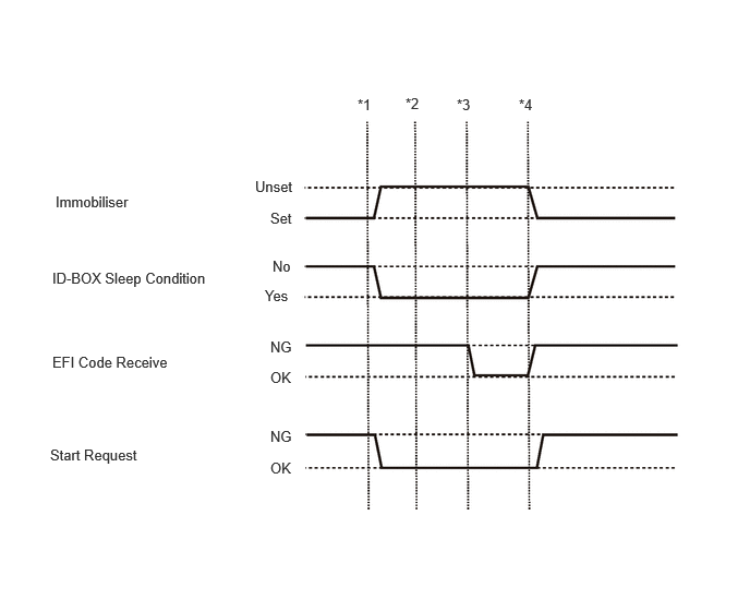
- HINT:
-
To check if the Data List display changes, get into the vehicle while carrying an electrical key transmitter sub-assembly and perform the following operations with the ignition switch off and the shift position in P.
- ·
*1: Press the engine switch with the brake pedal released and check that the ignition switch turns ACC.
·*2: Press the engine switch with the brake pedal released and check that the ignition switch turns ON.
·*3: Press the engine switch with the brake pedal released and check that the engine starts.
·*4: Press the engine switch and check that the ignition switch turns off.
- Body Electrical > Combination Meter > Data List
-
Tester Display Measurement Item Range Normal Condition Diagnostic Note Vehicle Speed Meter Vehicle speed Min.: 0, Max.: 255 Almost same as actual vehicle speed (Speedometer tester) -
- Chassis > Brake/EPB > Data List
-
Tester Display Measurement Item Range Normal Condition Diagnostic Note Vehicle Speed Vehicle speed Min.: 0.0 km/h (0 mph)
Max.: 6553.5 km/h (4072 mph)Vehicle stopped: 0.0 km/h (0 mph) When driving at constant speed: No large fluctuations
- Body Electrical > Main Body > Data List
-
Tester Display Measurement Item Range Normal Condition Diagnostic Note FR Door Courtesy Switch Status Front door RH courtesy light switch signal Close or Open Close: Front door RH closed
Open: Front door RH open- FL Door Courtesy Switch Status Front door LH courtesy light switch signal Close or Open Close: Front door LH closed
Open: Front door LH open- RR Door Courtesy Switch Status Rear door RH courtesy light switch signal Close or Open Close: Rear door RH closed
Open: Rear door RH open- RL Door Courtesy Switch Status Rear door LH courtesy light switch signal Close or Open Close: Rear door LH closed
Open: Rear door LH open-
- Powertrain > Engine > Data List
-
Tester Display Measurement Item Range Normal Condition Diagnostic Note Starter SW Starter signal ON or OFF ·ON: Starter operating
·OFF: Starter not operating
- Immobiliser Fuel Cut Status Status of immobiliser fuel cut OFF or ON - -
ACTIVE TEST
- HINT:
-
Using the GTS to perform Active Tests allows relays, VSVs, actuators and other items to be operated without removing any parts. This non-intrusive functional inspection can be very useful because intermittent operation may be discovered before parts or wiring is disturbed. Performing Active Tests early in troubleshooting is one way to save diagnostic time. Data List information can be displayed while performing Active Tests.
Perform Active Test according to the display on the GTS.
- Body Electrical > Entry&Start > Active Test
-
Tester Display Measurement Item Control Range Diagnostic Note Start SW Light Power Supply Engine switch light OFF/ON - Immobiliser Indicator Security indicator light OFF/ON -