STOP AND START STOP AND START SYSTEM Backup Boost Converter Circuit
DESCRIPTION
A backup boost converter is built into the engine stop and start ECU. The backup boost converter helps maintain the power source voltage when the engine is restarted by stop and start control.
This prevents various functions such as the audio and visual system from malfunctioning if the power source voltage drops due to the battery voltage dropping when the engine is restarted by stop and start control.
If any DTCs are output, troubleshoot the DTCs first.
- HINT:
-
A relay function and fuse function are provided in the backup boost converter.
-
If there is a malfunction in any of the electrical system circuits connected to the backup boost converter, the fuse and relay functions shut off the malfunctioning circuit to protect other circuits (remains shut off until next trip).
-
When the electrical system circuit is shut off, power to the circuit is cut off, causing any systems connected to the circuit to be disabled.
-
The fuse function is reset* when the ignition switch is turned off. If the malfunction still exists in the electrical system circuit that has been shut off by the relay function, it will be shut off again by the relay and fuse functions the next time the ignition switch is turned to ON.
-
*: A semiconductor fuse self resets according to electric signal.
- The backup boost converter supplies power to:·
Pre-collision system
·Tire pressure warning system
·Electronically controlled brake system
·Power steering system
·Audio and visual system
·CAN communication system
·Meter / gauge system
·Air conditioning system
·Digital rear-view mirror system
·Blind spot monitor system
·Headup display system
WIRING DIAGRAM
Refer to DTC P323A00.
CAUTION / NOTICE / HINT
- NOTICE:
- ·
Before replacing the engine stop and start ECU, read the number of starter operations and write it into a new engine stop and start ECU.
·After replacing the engine stop and start ECU or air conditioning amplifier assembly, reset and perform learning of the air conditioning information in the engine stop and start ECU.
·After replacing the engine stop and start ECU or airbag ECU assembly, clear and calibrate the deceleration sensor zero point in the engine stop and start ECU.
·Bleed the oil pump with motor assembly (continuously variable transaxle assembly) after removing and installing the continuously variable transaxle assembly or replacing the CVT fluid.
·Inspect the fuses for circuits related to this system before performing the following procedure.
PROCEDURE
Determine the trouble area by referring to the table below.
| Effect on Vehicle | Trouble Area/Cause | Fail-safe | DTC Output | Stop and start cancel indicator | Symptom | Proceed to |
|---|---|---|---|---|---|---|
| When the engine is restarted by stop and start control:
The following symptoms may occur ·
Audio and visual system is reset ·
The combination meter assembly fades out ·
The steering wheel feels heavy when the engine is restarted* |
Backup boost converter internal malfunction
·
Internal power source malfunction ·
Internal power source overvoltage ·
CPU duty malfunction ·
Communication cycle error |
Stop and start control prohibited | P323A00
P323B14 P323B29 P323B38 |
Blinks | Systems stop operating during engine restart as the backup boost converter output voltage cannot be boosted | A |
| Battery voltage drop | ||||||
| Systems on the converter output side do not operate
B41 terminal: Both of the following will not operate ·
Tire pressure warning system ·
Headup display system B42 terminal: Audio and visual system will not operate IG41 terminal: All of the following will not operate ·
Tire pressure warning system ·
Pre-collision system ·
Air conditioning system ·
Headup display system |
Overcurrent applied to an output terminal (output terminal relay circuit is shutoff) | Stop and start control is prohibited
(Connected ECUs or sensors may detect power source malfunction DTCs) |
X087A | Blinks | Systems do not operate as power supply from the converter is cut off | D |
| Systems do not operate
(Due to converter input side malfunction) IGR terminal: All of the following will not operate ·
Tire pressure warning system ·
Pre-collision system ·
Power steering system ·
Electronically Controlled Brake System ·
Air conditioning system ·
Headup display system IGP terminal: The meter/gauge system will not operate ACC terminal: Audio and visual system will not operate |
Converter input circuit malfunction
·
Open or short to GND in IGR circuit ·
Open or short to GND in IGP circuit ·
Open or short to GND in ACC circuit |
Stop and start control prohibited | - | Does not blink (Blinks when communication error DTCs are stored) | Systems do not operate as power supply from the converter is cut off | B |
| Systems on the converter output side do not operate
(varies depending on the malfunctioning relay circuit the converter detected) AC42 terminal: Audio and visual system will not operate IG12 terminal: The meter / gauge system will not operate IG31 terminal: Both of the following will not operate ·
Electronically controlled brake system ·
Power steering system ·
The power steering system will not operate IG41 terminal: All of the following will not operate ·
Tire pressure warning system ·
Pre-collision system ·
Air conditioning system ·
Headup display system B41 terminal: All of the following will not operate ·
Tire pressure warning system ·
Headup display system B42 terminal: Audio and visual system will not operate |
Malfunction in circuits the converter supplies power to
(between the converter and ECUs or sensors) |
Related systems do not operate as the relay circuit in the converter is turned off | - | Does not blink (Blinks when communication error DTCs are stored) | Systems do not operate as power supply from the converter is cut off | B |
| All of the following systems do not operate
·
Pre-collision system ·
Tire pressure warning system ·
Electronically controlled brake system ·
Power steering system ·
Audio and visual system ·
Meter / gauge system ·
Air conditioning system ·
Headup display system |
·
Open in BBC fuse circuit ·
Short in converter circuit ·
Backup boost converter malfunction |
Stop and start control prohibited | P061511 | Does not blink (Due to disabled meter / gauge system) | All systems that the converter supplies power to do not operate (see circuit diagram) | A |
| P323A00
P323B14 P323B14 P323B29 P323B38 |
||||||
| The audio does not operate
(until the ignition switch is turned off) |
Excessive audio volume
Data List item "State of BBC" displays "BBC Overcurrent" while the circuit is protected |
The relay circuit in the converter is turned off to cut off power supply to the audio and visual system (navigation system) (Returns to normal when the ignition switch is turned off) | - | Does not blink | If overcurrent is detected in the audio and visual system (navigation system), system operation is disabled while the ignition switch is ON
(Returns to normal when the ignition switch is turned off) |
C |
·
The combination meter assembly cannot be turned off (short between IG12 and +B) ·
Communication error DTCs may be stored due to short between AC42 and +B
|
Converter circuit malfunction
·
Short between IG12 and +B ·
Short between AC42 and +B |
- | - | Does not blink | The converter cannot shut off the power source when the ignition switch is turned off | B |
·
Ignition switch cannot be turned off from ACC (short between ACC and +B) ·
Ignition switch cannot be turned off from IG (short between IGR or IGP and +B) |
Engine stop and start ECU power source circuit malfunction
·
Short between ACC and +B ·
Short between IGR and +B ·
Short between IGP and +B |
- | - | Does not blink | Ignition switch cannot be turned off | B |
*: A DTC may be stored in the power steering system
- Result:
Proceed to A B C D
A
B
C
D
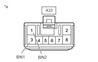
| *a | Front view of wire harness connector
(to Engine Stop and Start ECU) |
Disconnect the engine stop and start ECU connector.
Measure the voltage according to the value(s) in the table below.
- Standard Voltage:
Tester Connection Condition Specified Condition A33-1 (BIN2) - Body ground Always 9.5 to 14 V A33-3 (BIN1) - Body ground Always 9.5 to 14 V
- Result:
Proceed to OK NG
OK
NG
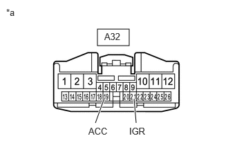
| *a | Front view of wire harness connector
(to Engine Stop and Start ECU) |
Disconnect the engine stop and start ECU connector.
Turn the ignition switch to ACC.
Measure the voltage according to the value(s) in the table below.
- Standard Voltage:
Tester Connection Condition Specified Condition A32-19 (ACC) - Body ground Ignition switch ACC 9.5 to 14 V
Turn the ignition switch to ON.
Measure the voltage according to the value(s) in the table below.
- Standard Voltage:
Tester Connection Condition Specified Condition A32-21 (IGR) - Body ground Ignition switch ON 9.5 to 14 V
Turn the ignition switch to off.
Measure the voltage according to the value(s) in the table below.
- Standard Voltage:
Tester Connection Condition Specified Condition A32-19 (ACC) - Body ground Ignition switch off 0 to 1 V A32-21 (IGR) - Body ground Ignition switch off 0 to 1 V
- Result:
Proceed to OK NG
OK
NG
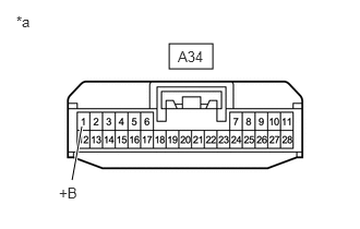
| *a | Front view of wire harness connector
(to Engine Stop and Start ECU) |
Disconnect the engine stop and start ECU connector.
Turn the ignition switch to ON.
Measure the voltage according to the value(s) in the table below.
- Standard Voltage:
Tester Connection Condition Specified Condition A34-1 (+B) - Body ground Ignition switch ON 9.5 to 14 V
Turn the ignition switch to off.
Measure the voltage according to the value(s) in the table below.
- Standard Voltage:
Tester Connection Condition Specified Condition A34-1 (+B) - Body ground Ignition switch off 0 to 1 V
- Result:
Proceed to OK NG
OK
NG
Disconnect the connector from the corresponding system ECU/sensor.
Measure the resistance according to the value(s) in the table below.
- Standard Resistance:
Power Steering ECU (Rack and Pinion Power Steering Gear Assembly) Tester Connection Condition Specified Condition A32-1 (IG31) - C54-4 (IG) Always Below 1 Ω A32-1 (IG31) or C54-4 (IG) - Body ground and other terminals Always 10 kΩ or higher
Combination Meter Assembly (except 12.3 Inch Display) Tester Connection Condition Specified Condition A32-10 (IG12) - G18-38 (IG+) Always Below 1 Ω A32-10 (IG12) or G18-38 (IG+) - Body ground and other terminals Always 10 kΩ or higher
Combination Meter Assembly (for 12.3 Inch Display) Tester Connection Condition Specified Condition A32-10 (IG12) - G151-6 (IG+) Always Below 1 Ω A32-10 (IG12) or G151-6 (IG+) - Body ground and other terminals Always 10 kΩ or higher
Radio and Display Receiver Assembly Tester Connection Condition Specified Condition A32-12 (B42) - G155-4 (+B1) Always Below 1 Ω A32-26 (AC42) - G155-16 (ACC1) Always Below 1 Ω A32-12 (B42) or G155-4 (+B1) - Body ground and other terminals Always 10 kΩ or higher A32-26 (AC42) or G155-16 (ACC1) - Body ground and other terminals Always 10 kΩ or higher
Tire Pressure Warning ECU and Receiver Tester Connection Condition Specified Condition A32-2 (B41) - M8-7 (+B) Always Below 1 Ω A32-3 (IG41) - M8-1 (IG) Always Below 1 Ω A32-2 (B41) or M8-7 (+B) - Body ground and other terminals Always 10 kΩ or higher A32-3 (IG41) or M8-1 (IG) - Body ground and other terminals Always 10 kΩ or higher
Millimeter Wave Radar Sensor Assembly (w/ Pre-collision System) Tester Connection Condition Specified Condition A32-3 (IG41) - B9-8 (IGB) Always Below 1 Ω A32-3 (IG41) or B9-8 (IGB) - Body ground and other terminals Always 10 kΩ or higher
Air Conditioning Control Assembly Tester Connection Condition Specified Condition A32-3 (IG41) - G24-9 (IG+) Always Below 1 Ω A32-25 (IL41) - G24-8 (ILL+) Always Below 1 Ω A32-3 (IG41) or G24-9 (IG+) - Body ground and other terminals Always 10 kΩ or higher A32-25 (IL41) or G24-8 (ILL+) - Body ground and other terminals Always 10 kΩ or higher
Skid Control ECU (Brake Actuator Assembly) Tester Connection Condition Specified Condition A32-1 (IG31) - A39-36 (IGR) Always Below 1 Ω A32-1 (IG31) or A39-36 (IGR) - Body ground and other terminals Always 10 kΩ or higher
Steering Sensor Tester Connection Condition Specified Condition A32-1 (IG31) - G68-9 (IGR) Always Below 1 Ω A32-1 (IG31) or G68-9 (IGR) - Body ground and other terminals Always 10 kΩ or higher
Meter Mirror Sub-assembly (w/ Headup Display System) Tester Connection Condition Specified Condition A32-2 (B41) - G138-2 (B) Always Below 1 Ω A32-3 (IG41) - G138-1 (IG) Always Below 1 Ω A32-2 (B41) or G138-2 (B) - Body ground and other terminals Always Below 1 Ω A32-3 (IG41) or G138-1 (IG) - Body ground and other terminals Always 10 kΩ or higher
- Result:
Proceed to OK NG
OK
NG
Disconnect the connector from the corresponding system ECU/sensor.
Measure the voltage according to the value(s) in the table below.
- HINT:
-
Measure the voltage at the corresponding terminals.
- Standard Voltage:
Tester Connection Condition Specified Condition M8-7 (+B) - Body ground Always 10.5 to 16 V G155-4 (+B1) - Body ground Always 10.5 to 16 V G138-2 (B) - Body ground* Always 10.5 to 16 V
*: w/ Headup Display System
Turn the ignition switch to ACC.
Measure the voltage according to the value(s) in the table below.
- HINT:
-
Measure the voltage at the corresponding terminals.
- Standard Voltage:
Tester Connection Condition Specified Condition G155-16 (ACC1) - Body ground Ignition switch ACC 10.5 to 16 V
Turn the ignition switch to ON.
Measure the voltage according to the value(s) in the table below.
- HINT:
-
Measure the voltage at the corresponding terminals.
- Standard Voltage:
Tester Connection Condition Specified Condition C54-4 (IG) - Body ground Ignition switch ON 10.5 to 16 V G18-38 (IG+) - Body ground*3 Ignition switch ON 10.5 to 16 V G151-6 (IG+) - Body ground*4 Ignition switch ON 10.5 to 16 V B9-8 (IGB) - Body ground*2 Ignition switch ON 10.5 to 16 V G24-9 (IG+) - Body ground Ignition switch ON 10.5 to 16 V M8-1 (IG) - Body ground Ignition switch ON 10.5 to 16 V A39-36 (IGR) - Body ground Ignition switch ON 10.5 to 16 V G68-9 (IGR) - Body ground Ignition switch ON 10.5 to 16 V G138-1 (IG) - Body ground*1 Ignition switch ON 10.5 to 16 V
*1: w/ Headup Display System
*2: w/ Pre-collision System
*3: except 12.3 Inch Display
*4: for 12.3 Inch Display
Turn the headlight dimmer switch (light control switch) to the tail or head position.
Measure the voltage according to the value(s) in the table below.
- HINT:
-
Measure the voltage at the corresponding terminals.
- Standard Voltage:
Tester Connection Condition Specified Condition G24-8 (ILL+) - Body ground Headlight dimmer switch (light control switch) in tail or head position 10.5 to 16 V
- Result:
Proceed to OK NG
OK
NG
Turn the ignition switch off and wait for 1 minute.
Turn the ignition switch to ON.
Lower the audio volume.
Check if the audio and visual system operates normally.
- OK:
Audio and visual system operates normally.
- Result:
Proceed to OK NG
OK
NG
Disconnect the engine stop and start ECU connector.
Disconnect the radio and display receiver assembly connector.
Measure the resistance according to the value(s) in the table below.
- Standard Resistance:
Tester Connection Condition Specified Condition A32-12 (B42) or G155-4 (+B1) - Body ground Always 10 kΩ or higher
- Result:
Result Proceed to OK A NG B
A
B
Disconnect the engine stop and start ECU connector.
Remove the BBC NO. 1 fuse and BBC NO. 2 fuse from the No. 1 engine room relay block and No. 1 junction block assembly.
Measure the resistance according to the value(s) in the table below.
- Standard Resistance:
Tester Connection Condition Specified Condition A33-1 (BIN2) - 2 (BBC NO. 2 fuse) Always Below 1 Ω A33-3 (BIN1) - 2 (BBC NO. 1 fuse) Always Below 1 Ω A33-1 (BIN2) or 2 (BBC NO. 2 fuse) - Body ground and other terminals Always 10 kΩ or higher A33-3 (BIN1) or 2 (BBC NO. 1 fuse) - Body ground and other terminals Always 10 kΩ or higher
- Result:
Proceed to OK NG
OK
NG
Disconnect the engine stop and start ECU connector.
Disconnect the tire pressure warning ECU and receiver connector.
Disconnect the radio and display receiver assembly connector.
Disconnect the millimeter wave radar sensor assembly connector. (w/ Pre-collision System)
Disconnect the air conditioning control assembly connector.
Disconnect the meter mirror sub-assembly connector. (w/ Headup Display System)
Measure the resistance according to the value(s) in the table below.
- Standard Resistance:
Tester Connection Condition Specified Condition A32-2 (B41) - M8-7 (+B) Always Below 1 Ω A32-3 (IG41) - M8-1 (IG) Always Below 1 Ω A32-12 (B42) - G155-4 (+B) Always Below 1 Ω A32-3 (IG41) - B9-8 (IGB)*1 Always Below 1 Ω A32-3 (IG41) - G24-9 (IG+) Always Below 1 Ω A32-2 (B41) - G138-2 (B)*2 Always Below 1 Ω A32-3 (IG41) - G138-1 (IG)*2 Always Below 1 Ω A32-2 (B41) or M8-7 (+B) - Body ground and other terminals Always 10 kΩ or higher A32-3 (IG41) or M8-1 (IG) - Body ground and other terminals Always 10 kΩ or higher A32-12 (B42) or G155-4 (+B) - Body ground and other terminals Always 10 kΩ or higher A32-3 (IG41) or B9-8 (IGB)*1 - Body ground and other terminals Always 10 kΩ or higher A32-3 (IG41) or G24-9 (IG+) - Body ground and other terminals Always 10 kΩ or higher A32-2 (B41) or G138-2 (B)*2 - Body ground and other terminals Always 10 kΩ or higher A32-3 (IG41) or G138-1 (IG)*2 - Body ground and other terminals Always 10 kΩ or higher
*1: w/ Pre-collision System
*2: w/ Headup Display System
- Result:
Proceed to OK NG
OK
NG

| *a | Component without harness connected
(Engine Stop and Start ECU) |
- | - |
Disconnect the engine stop and start ECU connectors.
Measure the resistance according to the value(s) in the table below.
- Standard Resistance:
Tester Connection Condition Specified Condition A32-2 (B41) - A34-6 (DGND) Always 10 kΩ or higher A32-3 (IG41) - A34-6 (DGND) Always 10 kΩ or higher A32-11 (B43) - A34-6 (DGND) Always 10 kΩ or higher A32-12 (B42) - A34-6 (DGND) Always 10 kΩ or higher
- Result:
Proceed to OK NG
OK
NG
Check that additional devices installed to the vehicle (aftermarket audio system, etc.) are not connected to the B41, B42, B43 or IG41 terminal circuit of the engine stop and start ECU.
- Result:
Result Proceed to Load from an additional device installed to the vehicle (aftermarket audio system, etc.) is not applied. A Load from an additional device installed to the vehicle (aftermarket audio system, etc.) is applied. B
A
B