K121 CVT CONTINUOUSLY VARIABLE TRANSAXLE SYSTEM TERMINALS OF ECU
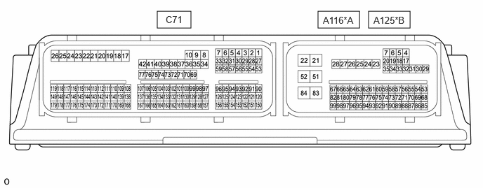
| *A | for SFTM Made | *B | for GTMC Made |
- HINT:
-
The standard voltage and resistance between each pair of ECM terminals is shown in the table below.
-
The appropriate conditions for checking each pair of terminals are also indicated. The result of checks should be compared with the standard voltage or resistance for that pair of terminals shown in the "Specified Condition" column.
-
Use the illustration above as a reference for the ECM terminals.
| Terminal No. (Symbol) | Terminal Description | Condition | Specified Condition |
|---|---|---|---|
|
*1: w/ Smart Entry and Start System *2: w/o Smart Entry and Start System |
|||
| A116-4 (CANH) - A116-22 (E1) | CAN communication line | Ignition switch ON | Pulse generation |
| A116-5 (CANL) - A116-22 (E1) | CAN communication line | Ignition switch ON | Pulse generation |
| A116-21 (+B) - A116-22 (E1) | Power source of ECM | Ignition switch ON | 11 to 14 V |
| A116-22 (E1) - Body ground | Ground | Always | Below 1 Ω |
| A116-31 (BATT) - A116-22 (E1) | Battery (for measuring battery voltage and ECM memory) | Always | 11 to 14 V |
| A116-51 (+B2) - A116-22 (E1) | Power source of ECM | Ignition switch ON | 11 to 14 V |
| A116-67 (PLKC) - A116-22 (E1) | Shift lock release request signal | Ignition switch ON, brake pedal depressed | 11 to 14 V |
| Ignition switch ON, brake pedal released | Below 1.5 V | ||
| A116-78 (SFTD) - A116-22 (E1) | Down-shift switch signal | ·
Ignition switch ON ·
Shift lever in M |
11 to 14 V |
·
Ignition switch ON ·
Shift lever held in "-" |
Below 1 V | ||
| A116-79 (SFTU) - A116-22 (E1) | Up-shift switch signal | ·
Ignition switch ON ·
Shift lever in M |
11 to 14 V |
·
Ignition switch ON ·
Shift lever held in "+" |
Below 1 V | ||
| A116-81 (PPOS) - A116-22 (E1)*1 | Shift state signal | Ignition switch ON, shift lever in P or N | 11 to 14 V |
| Ignition switch ON, shift lever not in P or N | Below 1 V | ||
| A116-82 (BL) - A116-22 (E1) | Back-up light relay | Ignition switch ON, shift lever in R | 11 to 14 V |
| A116-94 (SFT) - A116-22 (E1) | M position switch signal | Ignition switch ON, shift lever in M | 11 to 14 V |
| Ignition switch ON, shift lever not in M | Below 1 V | ||
| C71-1 (SC3) - A116-22 (E1) | Shift solenoid valve SC3 signal | Shift lever in R | 11 to 14 V |
| C71-2 (SC2) - A116-22 (E1) | Shift solenoid valve SC2 signal | ·
Vehicle being driven in Gear Mode ·
Shift lever in P |
11 to 14 V |
| C71-3 (SC1) - A116-22 (E1) | Shift solenoid valve SC1 signal | Shift lever in P, R or N | 11 to 14 V |
| C71-7 (SL2+) - C71-6 (SL2-) | Shift solenoid valve SL2 signal | Vehicle being driven in Belt Mode | Pulse generation |
| C71-30 (SLU+) - C71-31 (SLU-) | Shift solenoid valve SLU signal | Lock-up turned from OFF to ON | Pulse generation |
| C71-32 (NSR+) - C71-33 (NSR-)*2 | ST NO. 2 relay operation signal | Ignition switch ON, shift lever in P or N | 11 to 14 V |
| Ignition switch ON, shift lever not in P or N | Below 1 V | ||
| C71-54 (SLP+) - C71-55 (SLP-) | Shift solenoid valve SLP signal | Engine idling | Pulse generation |
| C71-56 (SL1+) - C71-57 (SL1-) | Shift solenoid valve SL1 signal | Vehicle being driven in gear mode | Pulse generation |
| C71-58 (SLS+) - C71-59 (SLS-) | Shift solenoid valve SLS signal | Engine idling | Pulse generation |
| C71-73 (INDB) - A116-22 (E1) | Shift position indicator signal | Ignition switch ON, shift lever in M | 0 to 3.2 V |
| Ignition switch ON, shift lever not in M | 11 to 14 V | ||
| C71-74 (INDD) - A116-22 (E1) | Shift position indicator signal | Ignition switch ON, shift lever in D | 0 to 3.2 V |
| Ignition switch ON, shift lever not in D | 11 to 14 V | ||
| C71-75 (INDN) - A116-22 (E1) | Shift position indicator signal | Ignition switch ON, shift lever in N | 0 to 3.2 V |
| Ignition switch ON, shift lever not in N | 11 to 14 V | ||
| C71-76 (INDR) - A116-22 (E1) | Shift position indicator signal | Ignition switch ON, shift lever in R | 0 to 3.2 V |
| Ignition switch ON, shift lever not in R | 11 to 14 V | ||
| C71-77 (INDP) - A116-22 (E1) | Shift position indicator signal | Ignition switch ON, shift lever in P | 0 to 3.2 V |
| Ignition switch ON, shift lever not in P | 11 to 14 V | ||
| C71-97 (NC1B) - A116-22 (E1) | Power source of transmission revolution sensor (NC1) | Ignition switch ON | 11 to 14 V |
| C71-98 (NC1O) - A116-22 (E1) | Transmission revolution sensor (NC1) signal | Vehicle being driven in Gear Mode | Pulse generation |
| C71-100 (NSSB) - A116-22 (E1) | Power source of transmission revolution sensor (NSS) | Ignition switch ON | 11 to 14 V |
| C71-101 (NSSO) - A116-22 (E1) | Transmission revolution sensor (NSS) signal | Vehicle being driven with shift lever in D | Pulse generation |
| C71-113 (PNB) - A116-22 (E1) | Shift lever position signal | Ignition switch ON, shift lever in P or N | 6 to 14 V |
| Ignition switch ON, shift lever not in P or N | 0 to 1.5 V | ||
| C71-114 (RP) - A116-22 (E1) | Shift lever position signal | Ignition switch ON, shift lever in P or R | 6 to 14 V |
| Ignition switch ON, shift lever not in P or R | 0 to 1.5 V | ||
| C71-115 (DB2) - A116-22 (E1) | Shift lever position signal | Ignition switch ON, shift lever in D | 6 to 14 V |
| Ignition switch ON, shift lever not in D | 0 to 1.5 V | ||
| C71-116 (DB1) - A116-22 (E1) | Shift lever position signal | Ignition switch ON, shift lever in D | 6 to 14 V |
| Ignition switch ON, shift lever not in D | 0 to 1.5 V | ||
| C71-117 (SPN) - A116-22 (E1) | Shift lever position signal | Ignition switch ON, shift lever in N | 6 to 14 V |
| Ignition switch ON, shift lever not in N | 0 to 1.5 V | ||
| C71-118 (SPR) - A116-22 (E1) | Shift lever position signal | Ignition switch ON, shift lever in R | 6 to 14 V |
| Ignition switch ON, shift lever not in R | 0 to 1.5 V | ||
| C71-119 (SPP) - A116-22 (E1) | Shift lever position signal | Ignition switch ON, shift lever in P | 6 to 14 V |
| Ignition switch ON, shift lever not in P | 0 to 1.5 V | ||
| C71-121 (VCPT) - C71-120 (EPTO) | Power source of oil pressure sensor | Ignition switch ON | 4.5 to 5.5 V |
| C71-122 (PTO) - C71-120 (EPTO) | Oil pressure sensor signal | Engine idling with shift lever in P | 0.28 to 4.9 V |
| C71-124 (SFV) - C71-123 (E2SF) | Shift stroke sensor signal | Synchronizer engaged | 0.622 to 1.393 V |
| Synchronizer not engaged | 3.587 to 4.429 V | ||
| C71-126 (THO1) - C71-125 (ETHO) | CVT fluid temperature sensor signal | CVT fluid temperature: 60 to 120°C (140 to 248°F) | 0.2 to 1.0 V |
| C71-150 (NOB) - A116-22 (E1) | Power source of transmission revolution sensor (NOUT) | Ignition switch ON | 11 to 14 V |
| C71-151 (NOO) - A116-22 (E1) | Transmission revolution sensor (NOUT) signal | Vehicle being driven with shift lever in D | Pulse generation |
| C71-152 (NTB) - A116-22 (E1) | Power source of transmission revolution sensor (NT) | Ignition switch ON | 11 to 14 V |
| C71-153 (NTO) - A116-22 (E1) | Transmission revolution sensor (NT) signal | Vehicle being driven with shift lever in D | Pulse generation |
| C71-154 (VCSF) - C71-123 (E2SF) | Power source of shift stroke sensor | Ignition switch ON | 4.5 to 5.5 V |
| Terminal No. (Symbol) | Terminal Description | Condition | Specified Condition |
|---|---|---|---|
|
*1: w/ Smart Entry and Start System *2: w/o Smart Entry and Start System |
|||
| A125-4 (CANH) - A125-22 (E1) | CAN communication line | Ignition switch ON | Pulse generation |
| A125-5 (CANL) - A125-22 (E1) | CAN communication line | Ignition switch ON | Pulse generation |
| A125-21 (+B) - A125-22 (E1) | Power source of ECM | Ignition switch ON | 11 to 14 V |
| A125-22 (E1) - Body ground | Ground | Always | Below 1 Ω |
| A125-31 (BATT) - A125-22 (E1) | Battery (for measuring battery voltage and ECM memory) | Always | 11 to 14 V |
| A125-51 (+B2) - A125-22 (E1) | Power source of ECM | Ignition switch ON | 11 to 14 V |
| A125-67 (PLKC) - A125-22 (E1) | Shift lock release request signal | Ignition switch ON, brake pedal depressed | 11 to 14 V |
| Ignition switch ON, brake pedal released | Below 1.5 V | ||
| A125-78 (SFTD) - A125-22 (E1) | Down-shift switch signal | ·
Ignition switch ON ·
Shift lever in M |
11 to 14 V |
·
Ignition switch ON ·
Shift lever held in "-" |
Below 1 V | ||
| A125-79 (SFTU) - A125-22 (E1) | Up-shift switch signal | ·
Ignition switch ON ·
Shift lever in M |
11 to 14 V |
·
Ignition switch ON ·
Shift lever held in "+" |
Below 1 V | ||
| A125-81 (PPOS) - A125-22 (E1)*1 | Shift state signal | Ignition switch ON, shift lever in P or N | 11 to 14 V |
| Ignition switch ON, shift lever not in P or N | Below 1 V | ||
| A125-82 (BL) - A125-22 (E1) | Back-up light relay | Ignition switch ON, shift lever in R | 11 to 14 V |
| A125-94 (SFT) - A125-22 (E1) | M position switch signal | Ignition switch ON, shift lever in M | 11 to 14 V |
| Ignition switch ON, shift lever not in M | Below 1 V | ||
| C71-1 (SC3) - A125-22 (E1) | Shift solenoid valve SC3 signal | Shift lever in R | 11 to 14 V |
| C71-2 (SC2) - A125-22 (E1) | Shift solenoid valve SC2 signal | ·
Vehicle being driven in Gear Mode ·
Shift lever in P |
11 to 14 V |
| C71-3 (SC1) - A125-22 (E1) | Shift solenoid valve SC1 signal | Shift lever in P, R or N | 11 to 14 V |
| C71-7 (SL2+) - C71-6 (SL2-) | Shift solenoid valve SL2 signal | Vehicle being driven in Belt Mode | Pulse generation |
| C71-30 (SLU+) - C71-31 (SLU-) | Shift solenoid valve SLU signal | Lock-up turned from OFF to ON | Pulse generation |
| C71-32 (NSR+) - C71-33 (NSR-)*2 | ST NO. 2 relay operation signal | Ignition switch ON, shift lever in P or N | 11 to 14 V |
| Ignition switch ON, shift lever not in P or N | Below 1 V | ||
| C71-54 (SLP+) - C71-55 (SLP-) | Shift solenoid valve SLP signal | Engine idling | Pulse generation |
| C71-56 (SL1+) - C71-57 (SL1-) | Shift solenoid valve SL1 signal | Vehicle being driven in gear mode | Pulse generation |
| C71-58 (SLS+) - C71-59 (SLS-) | Shift solenoid valve SLS signal | Engine idling | Pulse generation |
| C71-73 (INDB) - A125-22 (E1) | Shift position indicator signal | Ignition switch ON, shift lever in M | 0 to 3.2 V |
| Ignition switch ON, shift lever not in M | 11 to 14 V | ||
| C71-74 (INDD) - A125-22 (E1) | Shift position indicator signal | Ignition switch ON, shift lever in D | 0 to 3.2 V |
| Ignition switch ON, shift lever not in D | 11 to 14 V | ||
| C71-75 (INDN) - A125-22 (E1) | Shift position indicator signal | Ignition switch ON, shift lever in N | 0 to 3.2 V |
| Ignition switch ON, shift lever not in N | 11 to 14 V | ||
| C71-76 (INDR) - A125-22 (E1) | Shift position indicator signal | Ignition switch ON, shift lever in R | 0 to 3.2 V |
| Ignition switch ON, shift lever not in R | 11 to 14 V | ||
| C71-77 (INDP) - A125-22 (E1) | Shift position indicator signal | Ignition switch ON, shift lever in P | 0 to 3.2 V |
| Ignition switch ON, shift lever not in P | 11 to 14 V | ||
| C71-97 (NC1B) - A125-22 (E1) | Power source of transmission revolution sensor (NC1) | Ignition switch ON | 11 to 14 V |
| C71-98 (NC1O) - A125-22 (E1) | Transmission revolution sensor (NC1) signal | Vehicle being driven in Gear Mode | Pulse generation |
| C71-100 (NSSB) - A125-22 (E1) | Power source of transmission revolution sensor (NSS) | Ignition switch ON | 11 to 14 V |
| C71-101 (NSSO) - A125-22 (E1) | Transmission revolution sensor (NSS) signal | Vehicle being driven with shift lever in D | Pulse generation |
| C71-113 (PNB) - A125-22 (E1) | Shift lever position signal | Ignition switch ON, shift lever in P or N | 6 to 14 V |
| Ignition switch ON, shift lever not in P or N | 0 to 1.5 V | ||
| C71-114 (RP) - A125-22 (E1) | Shift lever position signal | Ignition switch ON, shift lever in P or R | 6 to 14 V |
| Ignition switch ON, shift lever not in P or R | 0 to 1.5 V | ||
| C71-115 (DB2) - A125-22 (E1) | Shift lever position signal | Ignition switch ON, shift lever in D | 6 to 14 V |
| Ignition switch ON, shift lever not in D | 0 to 1.5 V | ||
| C71-116 (DB1) - A125-22 (E1) | Shift lever position signal | Ignition switch ON, shift lever in D | 6 to 14 V |
| Ignition switch ON, shift lever not in D | 0 to 1.5 V | ||
| C71-117 (SPN) - A125-22 (E1) | Shift lever position signal | Ignition switch ON, shift lever in N | 6 to 14 V |
| Ignition switch ON, shift lever not in N | 0 to 1.5 V | ||
| C71-118 (SPR) - A125-22 (E1) | Shift lever position signal | Ignition switch ON, shift lever in R | 6 to 14 V |
| Ignition switch ON, shift lever not in R | 0 to 1.5 V | ||
| C71-119 (SPP) - A125-22 (E1) | Shift lever position signal | Ignition switch ON, shift lever in P | 6 to 14 V |
| Ignition switch ON, shift lever not in P | 0 to 1.5 V | ||
| C71-121 (VCPT) - C71-120 (EPTO) | Power source of oil pressure sensor | Ignition switch ON | 4.5 to 5.5 V |
| C71-122 (PTO) - C71-120 (EPTO) | Oil pressure sensor signal | Engine idling with shift lever in P | 0.28 to 4.9 V |
| C71-124 (SFV) - C71-123 (E2SF) | Shift stroke sensor signal | Synchronizer engaged | 0.622 to 1.393 V |
| Synchronizer not engaged | 3.587 to 4.429 V | ||
| C71-126 (THO1) - C71-125 (ETHO) | CVT fluid temperature sensor signal | CVT fluid temperature: 60 to 120°C (140 to 248°F) | 0.2 to 1.0 V |
| C71-150 (NOB) - A125-22 (E1) | Power source of transmission revolution sensor (NOUT) | Ignition switch ON | 11 to 14 V |
| C71-151 (NOO) - A125-22 (E1) | Transmission revolution sensor (NOUT) signal | Vehicle being driven with shift lever in D | Pulse generation |
| C71-152 (NTB) - A125-22 (E1) | Power source of transmission revolution sensor (NT) | Ignition switch ON | 11 to 14 V |
| C71-153 (NTO) - A125-22 (E1) | Transmission revolution sensor (NT) signal | Vehicle being driven with shift lever in D | Pulse generation |
| C71-154 (VCSF) - C71-123 (E2SF) | Power source of shift stroke sensor | Ignition switch ON | 4.5 to 5.5 V |