☰ Toyota Wildlander☰ فهرستAudio / Visual / Telematics › PARK ASSIST / MONITORING › BLIND SPOT MONITOR SYSTEM
RM36D0EC
_56
Audio / Visual / Telematics
_083082
PARK ASSIST / MONITORING
_0711992
BLIND SPOT MONITOR SYSTEM
J
PARK ASSIST / MONITORING BLIND SPOT MONITOR SYSTEM Power Source Circuit
DESCRIPTION
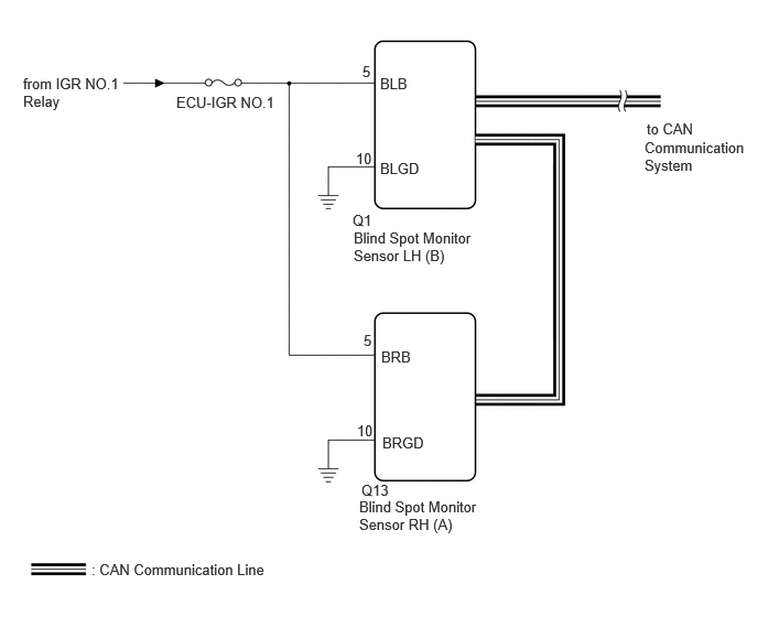
This circuit provides power to operate the blind spot monitor sensor.
WIRING DIAGRAM
0.865,5.302 2.99,5.51
2.125,0.208
10
false
: CAN Communication Line
6.115,1.135 6.625,1.333
0.51,0.198
10
false
to CAN
3.344,2.167 4.531,2.75
1.188,0.583
10
false
Blind Spot Monitor Sensor LH (B)
3.396,4.708 4.573,5.25
1.177,0.542
10
false
Blind Spot Monitor Sensor RH (A)
0.219,0.708 1.156,1.26
0.938,0.552
10
false
from IGR NO.1 Relay
3.594,0.708 4.188,0.99
0.594,0.281
10
false
BLB
3.594,1.51 4.188,1.792
0.594,0.281
10
false
BLGD
3.427,0.594 4.021,0.875
0.594,0.281
10
false
5
3.365,1.417 3.958,1.698
0.594,0.281
10
false
10
3.333,2 3.927,2.281
0.594,0.281
10
false
Q1
3.417,4.552 4.01,4.833
0.594,0.281
10
false
Q13
3.604,3.292 4.198,3.573
0.594,0.281
10
false
BRB
3.615,4.104 4.208,4.385
0.594,0.281
10
false
BRGD
3.438,3.135 4.031,3.417
0.594,0.281
10
false
5
3.375,3.99 3.969,4.271
0.594,0.281
10
false
10
1.667,0.885 3.063,1.219
1.396,0.333
10
false
ECU-IGR NO.1
6.094,1.313 7.073,2
0.979,0.688
10
false
Communication System
CAUTION / NOTICE / HINT
- HINT:
-
Inspect the fuses for circuits related to this system before performing the following procedure.
PROCEDURE
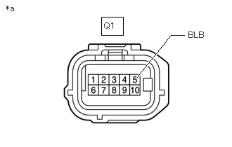
1.CHECK HARNESS AND CONNECTOR (BLIND SPOT MONITOR SENSOR LH [B] POWER SOURCE)
a.
1.5,0.25 1.823,0.521
0.323,0.271
2.021,1.156 2.531,0.521
2.531,0.521 2.729,0.521
true
0.083,0.052 0.396,0.25
0.313,0.198
10
false
*a
1.542,0.313 1.854,0.51
0.313,0.198
10
false
Q1
2.792,0.448 3.156,0.656
0.365,0.208
10
false
BLB
| *a | Front view of wire harness connector
(to Blind Spot Monitor Sensor LH [B]) |
Disconnect the blind spot monitor sensor LH (B) connector.
b.
Measure the voltage according to the value(s) in the table below.
- Standard Voltage:
Tester Connection Switch Condition Specified Condition Q1-5 (BLB) - Body ground Ignition switch ON 11 to 14 V Q1-5 (BLB) - Body ground Ignition switch off Below 1 V
- Result:
Proceed to OK NG
OK
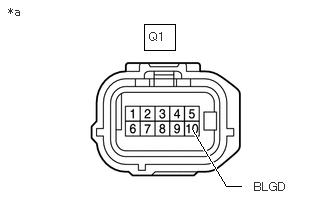
2.CHECK HARNESS AND CONNECTOR (BLIND SPOT MONITOR SENSOR LH [B] - BODY GROUND)
NG
REPAIR OR REPLACE HARNESS OR CONNECTOR
2.CHECK HARNESS AND CONNECTOR (BLIND SPOT MONITOR SENSOR LH [B] - BODY GROUND)
a.
1.5,0.25 1.823,0.521
0.323,0.271
2,1.344 2.354,1.938
2.354,1.938 2.51,1.938
true
0.083,0.052 0.396,0.25
0.313,0.198
10
false
*a
1.552,0.313 1.865,0.51
0.313,0.198
10
false
Q1
2.646,1.875 3.083,2.063
0.438,0.188
10
false
BLGD
| *a | Front view of wire harness connector
(to Blind Spot Monitor Sensor LH [B]) |
Disconnect the blind spot monitor sensor LH (B) connector.
b.
Measure the resistance according to the value(s) in the table below.
- Standard Resistance:
Tester Connection Condition Specified Condition Q1-10 (BLGD) - Body ground Always Below 1 Ω
- Result:
Proceed to OK NG
OK
3.CHECK HARNESS AND CONNECTOR (BLIND SPOT MONITOR SENSOR RH [A] POWER SOURCE)
NG
REPAIR OR REPLACE HARNESS OR CONNECTOR
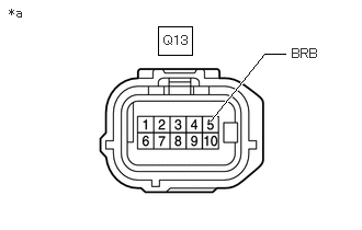
3.CHECK HARNESS AND CONNECTOR (BLIND SPOT MONITOR SENSOR RH [A] POWER SOURCE)
a.
1.5,0.25 1.823,0.521
0.323,0.271
2,1.146 2.51,0.51
2.51,0.51 2.708,0.51
true
0.083,0.052 0.396,0.25
0.313,0.198
10
false
*a
1.552,0.313 1.865,0.51
0.313,0.198
10
false
Q13
2.771,0.438 3.177,0.625
0.406,0.188
10
false
BRB
| *a | Front view of wire harness connector
(to Blind Spot Monitor Sensor RH [A]) |
Disconnect the blind spot monitor sensor RH (A) connector.
b.
Measure the voltage according to the value(s) in the table below.
- Standard Voltage:
Tester Connection Switch Condition Specified Condition Q13-5 (BRB) - Body ground Ignition switch ON 11 to 14 V Q13-5 (BRB) - Body ground Ignition switch off Below 1 V
- Result:
Proceed to OK NG
OK
4.CHECK HARNESS AND CONNECTOR (BLIND SPOT MONITOR SENSOR RH [A] - BODY GROUND)
NG
REPAIR OR REPLACE HARNESS OR CONNECTOR
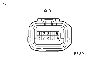
4.CHECK HARNESS AND CONNECTOR (BLIND SPOT MONITOR SENSOR RH [A] - BODY GROUND)
a.
1.5,0.25 1.927,0.521
0.427,0.271
2.042,1.354 2.365,1.865
2.365,1.865 2.51,1.865
true
0.083,0.052 0.396,0.25
0.313,0.198
10
false
*a
1.552,0.313 1.865,0.51
0.313,0.198
10
false
Q13
2.604,1.823 3.063,2.01
0.458,0.188
10
false
BRGD
| *a | Front view of wire harness connector
(to Blind Spot Monitor Sensor RH [A]) |
Disconnect the blind spot monitor sensor RH (A) connector.
b.
Measure the resistance according to the value(s) in the table below.
- Standard Resistance:
Tester Connection Condition Specified Condition Q13-10 (BRGD) - Body ground Always Below 1 Ω
- Result:
Proceed to OK NG
OK
PROCEED TO NEXT SUSPECTED AREA SHOWN IN PROBLEM SYMPTOMS TABLE
NG
REPAIR OR REPLACE HARNESS OR CONNECTOR