M20C-FKS STARTING STARTER REMOVAL
CAUTION / NOTICE / HINT
The necessary procedures (adjustment, calibration, initialization or registration) that must be performed after parts are removed and installed, or replaced during starter assembly removal/installation are shown below.
| Replaced Part or Performed Procedure | Necessary Procedure | Effect/Inoperative Function when Necessary Procedure not Performed | Link |
|---|---|---|---|
Starter assembly
|
Clear the number of starter operations | Stop and Start System | ( 202409,999999,_51,_083056,_0402418,RM100000002NSFT,) 202409,999999,_51,_083056,_0402418,RM100000002NSFT,)
|
- HINT:
-
When the cable is disconnected / reconnected to the battery terminal, systems temporarily stop operating. However, each system has a function that completes learning the first time the system is used.
- ·
Learning completes when vehicle is driven
Effect/Inoperative when not Performed Necessary Procedures Link Stop and start system Drive the vehicle until stop and start control is permitted (approximately 5 to 60 minutes). ( 202409,999999,_51,_083056,_0402418,RM100000002NSFO,)
Lane tracing assist system Drive the vehicle straight ahead at 15 km/h (10 mph) or more for 1 second or more. ( 201910,999999,_58,_083101,_0401880,RM100000001JE9I,)
Pre-collision system
·Learning completes when vehicle is operated normally
Effect/Inoperative when not Performed Necessary Procedures Link *: w/ Power back door system
Power back door function* Fully close the back door by hand.
- HINT:
-
Initialization is not necessary if the above procedures are performed while the back door is closed.
( 202304,999999,_59,_083093,_0584672,RM1000000029PGT,)
Power door lock control system If the back door is locked and therefore cannot be opened, it is necessary to unlock the back door using the door control switch, electrical key transmitter sub-assembly switch. ( 202409,999999,_58,_083092,_0403003,RM100000002NS90,)
Air conditioning system After the ignition switch is turned to ON, the servo motor standard position is recognized -
PROCEDURE

 1. PRECAUTION
- NOTICE:
- ·
After turning the engine switch off, waiting time may be required before disconnecting the cable from the negative (-) battery terminal. Therefore, make sure to read the disconnecting the cable from the negative (-) battery terminal notices before proceeding with work.
·When the starter assembly is replaced, "ST NO. 1 relay" must also be replaced.
2.DISCONNECT CABLE FROM NEGATIVE BATTERY TERMINAL
12361A
3.REMOVE FRONT ENGINE MOUNTING INSULATOR
12601B
4.REMOVE NO. 1 ENGINE COVER SUB-ASSEMBLY
17751
5.REMOVE NO. 1 INLET AIR CLEANER
6.REMOVE AIR CLEANER ASSEMBLY WITH AIR CLEANER HOSE
11363A
7.REMOVE FLYWHEEL HOUSING SIDE COVER

Detach the claw as shown in the illustration to remove the flywheel housing side cover.
28100
8.REMOVE STARTER ASSEMBLY
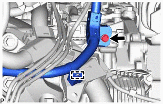
Detach the clamp, remove the bolt and disconnect the engine wire.
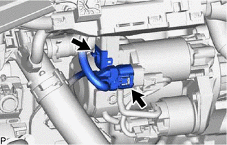
Disconnect the starter assembly connector.
Open the terminal cap.
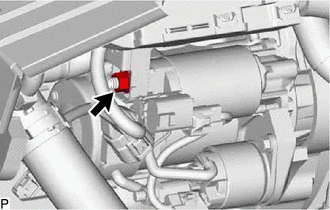
Remove the nut and disconnect the engine wire from terminal 30.
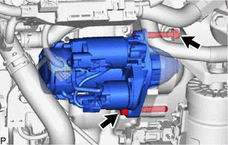
Remove the 2 bolts and starter assembly from the cylinder block sub-assembly.