HYBRID / BATTERY CONTROL HYBRID CONTROL SYSTEM Cooling System
DESCRIPTION
The cause of the malfunction may be the cooling system.
Check whether the grille is blocked, whether coolant is leaking, the radiator fan operating condition and whether coolant has frozen.
| Area | Inspection |
|---|---|
| Grille blockage, coolant amount, coolant hoses, radiator fan | Check for overheating due to hybrid cooling system malfunction. |
| Inverter coolant temperature sensor (built-in inverter) | Check for temperature sensor malfunction. |
| Coolant freezing check | Check freeze frame values to determine whether the hybrid coolant was frozen when the DTC was stored. |
| Data List |
|---|
·
Inverter Coolant Water Temperature ·
Motor Inverter Temperature ·
Rear Motor Inverter Temperature ·
Generator Inverter Calculated Temperature ·
Boosting Converter Temperature (Upper) ·
Boosting Converter Temperature (Lower) ·
Ambient Temperature ·
Inverter Water Pump Revolution |
SYSTEM DESCRIPTION
The inverter converts the high-voltage direct current of the HV battery into alternating current for the generator (MG1), motor (MG2) and rear motor (MGR). The inverter generates heat during the conversion process. Therefore, the inverter is cooled by a special cooling system consisting of the inverter water pump assembly, the cooling fan, and a radiator. This cooling system is independent of the engine cooling system. The hybrid vehicle control ECU assembly monitors the inverter water pump assembly, cooling fan and cooling system, and detects malfunctions.
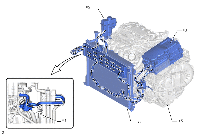
| *1 | Inverter Water Pump Assembly | *2 | Inverter Reserve Tank Assembly |
| *3 | Inverter with Converter Assembly | *4 | Radiator Assembly (HV) |
| *5 | Hybrid Vehicle Transaxle Assembly | - | - |
WIRING DIAGRAM
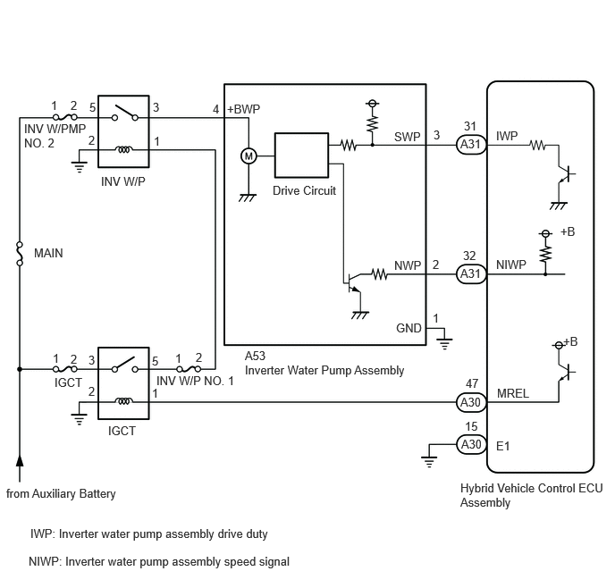
CAUTION / NOTICE / HINT
This diagnostic procedure is referenced to in the diagnostic procedure of several DTCs.
If the result of this diagnostic procedure is normal, proceed as directed in the procedure for the DTC.
- CAUTION:
-
Refer to the precautions before inspecting high voltage circuit.
PROCEDURE
Make sure that the front side of the radiator grille is not blocked with anything.
Ask the customer if the front side of the radiator grille was blocked with anything.
- Result:
Result Proceed to Not blocked. A Is/was blocked. B
- HINT:
-
If the radiator grille is blocked, the inverter coolant temperature will increase and this DTC may be stored.
A
B
Check the HV coolant level in the inverter reserve tank.
Check for HV coolant leaks.
- Result:
Result Proceed to No leaks are found and the HV coolant level in the inverter reserve tank assembly is above the low line. A No leaks are found and the HV coolant level in the inverter reserve tank assembly is below the low line. B HV coolant leaks are evident. C
- HINT:
- ·
After repairing the HV coolant leaks and adding coolant, perform the Active Tests "Activate the Inverter Water Pump" (Hybrid Control System) and "Control the Cooling Fan Duty Ratio" (Engine Control System) and make sure that there are no malfunctions.
·If there are signs of coolant leakage around the connecting parts of a hose and the inverter with converter assembly, replace the hose with a new one.
A
B
C
Check that the cooling system hoses are not kinked or clogged.
- OK:
The cooling system hoses are not kinked or clogged.
- Result:
Proceed to OK NG
OK
NG
Connect the GTS to the DLC3.
Turn the power switch on (IG).
Enter the following menus: Powertrain / Engine / Active Test / Control the Engine Cooling Fan Duty Ratio.
- Powertrain > Engine > Active Test
-
Tester Display Control the Engine Cooling Fan Duty Ratio - 50004 372 11
Perform the "Control the Engine Cooling Fan Duty Ratio" Active Test.
- OK:
Tester Operation Fan Operation 30 - 100% Cooling fan operates 0% Cooling fan stops
- Result:
Result Proceed to Cooling fan operate A Cooling fan does not operate B Cooling fan do not stop
Turn the power switch off.
A
B
for A25B-FXS:
for A25D-FXS:
for A25F-FXS:
- NOTICE:
- ·
Make sure that the HV coolant level is above the low line of the inverter reserve tank.
·Be sure to perform the inspection with the auxiliary battery voltage at 11 V or more.
- HINT:
-
When the auxiliary battery voltage is low, the inverter water pump assembly may not operate.
Connect the GTS to the DLC3.
Turn the power switch on (IG).
Enter the following menus: Powertrain / Hybrid Control / Active Test / Activate the Inverter Water Pump.
- Powertrain > Hybrid Control > Active Test
-
Active Test Display Activate the Inverter Water Pump -
Data List Display Inverter Water Pump Revolution - 50004 397 1 60
Select the Data List item "Inverter Water Pump Revolution".
According to the display on the GTS, perform the Active Test "Activate the Inverter Water Pump" and check the value of the Data List item "Inverter Water Pump Revolution".
- OK:
Tester Display Condition Specified Condition Inverter Water Pump Revolution Power switch on (IG)
During Active Test3000 to 9500 rpm
- HINT:
- ·
Perform the Active Test with the inverter coolant temperature between -15 and 65°C (5 to 149°F).
·When the inverter water pump assembly is not operating, the Data List item "Inverter Water Pump Revolution" displays a value 200 rpm or less.
Turn the power switch off.
- Result:
Proceed to OK NG
OK
NG
Connect the GTS to the DLC3.
Turn the power switch on (READY) and wait for 1 minute with the engine stopped.
Enter the following menus: Powertrain / Hybrid Control / Data List / Generator Inverter Calculated Temperature, Motor Inverter Temperature, Rear Motor Inverter Temperature, Boosting Converter Temperature (Upper), Boosting Converter Temperature (Lower) and Inverter Coolant Water Temperature.
- Powertrain > Hybrid Control > Data List
-
Tester Display Generator Inverter Calculated Temperature Motor Inverter Temperature Rear Motor Inverter Temperature Boosting Converter Temperature (Upper) Boosting Converter Temperature (Lower) Inverter Coolant Water Temperature - 50003 397 127,130,133,136,137,152
Read the Data List with the engine stopped.
- Result:
Result Proceed to Other than below. A "Inverter Coolant Water Temperature" value is higher than the displayed temperature of any other Data List item by 20°C (68°F) or more. B
- HINT:
-
The lower limit temperature that can be displayed for "Generator Inverter Calculated Temperature", "Motor Inverter Temperature", "Boosting Converter Temperature (Upper)" and "Boosting Converter Temperature (Lower)" is 0°C (32°F). The lower limit temperature for "Inverter Coolant Water Temperature" is -40°C (-40°F). The "Inverter Coolant Water Temperature" value displayed on the GTS may be lower than the others, but this is not a malfunction.
Turn the power switch off.
A
B
for 2WD:
for AWD:
Connect the GTS to the DLC3.
Turn the power switch on (IG).
Enter the following menus: Powertrain / Hybrid Control / Trouble Codes.
- Powertrain > Hybrid Control > Trouble Codes
- 50001 397
Read the freeze frame data item "Ambient Temperature" using the GTS.
Check if the freeze frame data item "Ambient Temperature" is below the freezing temperature of the HV coolant.
- Result:
Result Proceed to Ambient Temperature value is above freezing temperature of the HV coolant. A Ambient Temperature value is below freezing temperature of the HV coolant. B
- HINT:
- ·
HV coolant (SLLC) with a 30% concentration freezes at -15°C (5°F) and HV coolant (SLLC) with a 50% concentration freezes at -35°C (-31°F).
·If the HV coolant freezes in the HV radiator or inverter water pump, the coolant temperature in the inverter with converter assembly rises because the HV coolant cannot circulate. As a result, a DTC may be stored.
·A DTC is stored when the inverter water pump impeller cannot rotate due to freezing of the HV coolant.
·If DTCs are output due to freezing of the LLC, the problem symptom cannot be reproduced. Check the LLC replacement history and whether the LLC was frozen based on the ambient temperature when the DTCs were stored.
Turn the power switch off.
A
B
- Result:
Proceed to OK NG
OK
NG
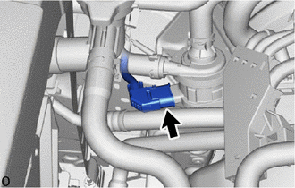
Check the connector connections and contact pressure of the relevant terminals for the inverter water pump assembly connector.
- OK:
The connector is connected securely, the terminals are not deformed or corroded and there are no contact problems.
- Result:
Proceed to OK NG
OK
NG
Disconnect the A31 hybrid vehicle control ECU assembly connector.
Disconnect the A53 inverter water pump assembly connector.
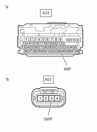
| *a | Front view of wire harness connector
(to Hybrid Vehicle Control ECU Assembly) |
| *b | Front view of wire harness connector
(to Inverter Water Pump Assembly) |
Measure the resistance according to the value(s) in the table below.
- Standard Resistance (Check for Open):
Tester Connection Condition Specified Condition A31-31 (IWP) - A53-3 (SWP) Power switch off Below 1 Ω
- Standard Resistance (Check for Short):
Tester Connection Condition Specified Condition A31-31 (IWP) or A53-3 (SWP) - Body ground and other terminals Power switch off 10 kΩ or higher
Reconnect the A53 inverter water pump assembly connector.
Reconnect the A31 hybrid vehicle control ECU assembly connector.
- Result:
Proceed to OK NG
OK
NG
- NOTICE:
-
Be sure to perform the inspection with the auxiliary battery voltage at 11 V or more.
- HINT:
-
When the auxiliary battery voltage is low, the inverter water pump assembly may not operate.
Connect the GTS to the DLC3.
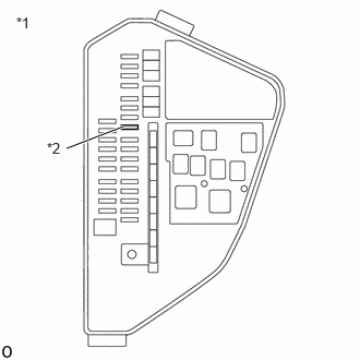
| *1 | No. 1 Engine Room Relay Block and Junction Block Assembly |
| *2 | INV W/PMP NO. 2 Fuse |
Remove the INV W/PMP NO. 2 fuse from No. 1 engine room relay block and junction block assembly.
Turn the power switch on (IG).
Enter the following menus: Powertrain / Hybrid Control / Data List / Inverter Water Pump Revolution.
- Powertrain > Hybrid Control > Data List
-
Tester Display Inverter Water Pump Revolution - 50003 397 60
According to the display on the GTS, read the Data List.
- OK:
Tester Display Condition Specified Condition Inverter Water Pump Revolution Power switch on (IG) 200 rpm or less
Turn the power switch off.
Install the INV W/PMP NO. 2 fuse.
- Result:
Proceed to OK NG
OK
NG
Disconnect the A31 and A30 hybrid vehicle control ECU assembly connector.
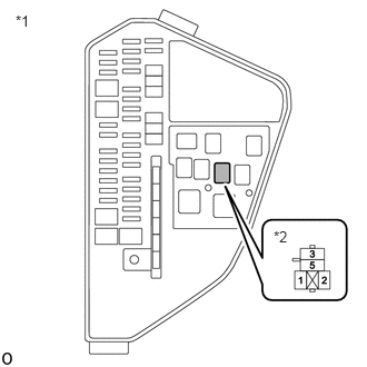
| *1 | No. 1 Engine Room Relay Block and Junction Block Assembly |
| *2 | INV W/P Relay Holder |
Remove the INV W/P relay from No. 1 engine room relay block and junction block assembly.
Connect terminals 3 and 5 of the INV W/P relay holder.
- HINT:
-
Make a short circuit between terminals 3 and 5 to supply +B voltage to the inverter water pump.
Measure the voltage according to the value(s) in the table below.
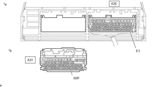
| *a | Component with harness connected
(Hybrid Vehicle Control ECU Assembly) |
*b | Front view of wire harness connector
(to Hybrid Vehicle Control ECU Assembly) |
- Standard Voltage:
Tester Connection Condition Specified Condition A31-31 (IWP) - A30-3 (E1) INV W/P relay holder terminals 3 and 5 connected
Power switch off11 to 14 V
- NOTICE:
-
Make sure to check for and clear DTCs after performing this inspection.
Install the INV W/P relay.
Reconnect the A31 and A30 hybrid vehicle control ECU assembly connector.
- Result:
Proceed to OK NG
OK
NG
Connect an oscilloscope between the hybrid vehicle control ECU assembly terminals specified in the table below.
Turn the power switch on (IG).
Check the waveform while turning the power switch on (IG).
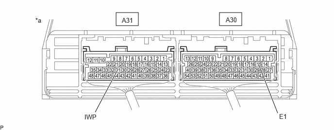
| *a | Component with harness connected
(Hybrid Vehicle Control ECU Assembly) |
- | - |
| Item | Content |
|---|---|
| Terminal | A31-31 (IWP) - A30-15 (E1) |
| Equipment Setting | 5 V/DIV., 50 ms./DIV. |
| Condition | Power switch on (IG) |
- OK:
Waveform duty ratio is between 3% and 9%.
Turn the power switch off.
- Result:
Proceed to OK NG
OK
NG
- Result:
Proceed to NEXT
NEXT
After replacing the inverter water pump assembly, add HV coolant and perform air bleeding.
- Result:
Proceed to NEXT
NEXT