HYBRID / BATTERY CONTROL HYBRID CONTROL SYSTEM Generator Resolver Circuit
DESCRIPTION
The cause of this malfunction may be the generator resolver.
Check the generator resolver internal resistance and connection condition from the inverter to the resolver.
| Area | Inspection |
|---|---|
| Wire harness and connector between the inverter and generator resolver | Check for short circuit between wire harness and +B side. |
| Resolver, wire harness, connector | Check the resolver wire harness internal resistance, body ground resistance, and connector connection condition. |
| Resolver | Check for open or short circuit of the resolver |
SYSTEM DESCRIPTION
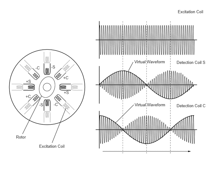
A resolver is a sensor that is used to detect the position of the magnetic poles of the rotor of a generator. Knowing the position of the poles is indispensable for ensuring precise control of the generator (MG1).
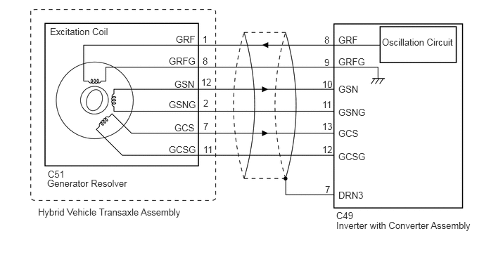
Each resolver contains a stator that has an excitation coil and 2 detection coils (S, C). The gap between the stator and rotor changes as the rotor turns because the rotor is oval shaped. An alternating current with a predetermined frequency flows through the excitation coil, and detection coils S and C output alternating currents in accordance with the sensor rotor position.
The MG ECU, which is built into the inverter with converter assembly, detects the absolute position of the rotor according to the phases of detection coils S and C and the heights of their waveforms. Furthermore, the CPU calculates the amount of change in the position within a predetermined length of time, in order to use the resolver as a revolution speed sensor.
The MG ECU monitors signals output from the generator resolver and detects malfunctions.
WIRING DIAGRAM
CAUTION / NOTICE / HINT
This diagnostic procedure is referenced to in the diagnostic procedure of several DTCs.
If the result of this diagnostic procedure is normal, proceed as directed in the procedure for the DTC.
- CAUTION:
-
Refer to the precautions before inspecting high voltage circuit.
- HINT:
- ·
If the problem symptom cannot be reproduced, performing a road test on a road on which the vehicle tends to vibrate will make it easier to reproduce the symptom.
·If the resolver is malfunctioning, the vehicle may not drive smoothly.
·When inspecting the connectors, if it is difficult to judge if a connector was disconnected, deformed or improperly secured, disconnect and reconnect the connector and then check for DTCs again. Check if the same DTC is output. If the same DTC is not output, improper connection of connectors is suspected.
·As a malfunction detection threshold may be exceeded when performing the vibration or heat connector inspections, make sure to perform the following inspection to check that the DTC was not stored due to the malfunction of a part.
PROCEDURE
- CAUTION:
-
Be sure to wear insulated gloves.
Check that the service plug grip is not installed.
- NOTICE:
-
After removing the service plug grip, do not turn the power switch on (READY), unless instructed by the repair manual because this may cause a malfunction.
Disconnect the C49 inverter with converter assembly connector.
Connect the cable to the negative (-) auxiliary battery terminal.
Turn the power switch on (IG).
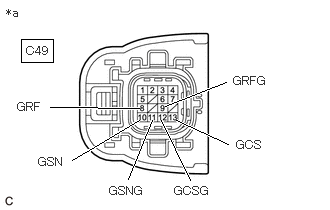
| *a | Front view of wire harness connector
(to Inverter with Converter Assembly) |
Measure the voltage according to the value(s) in the table below.
- Standard Voltage:
Tester Connection Condition Specified Condition C49-8 (GRF) - Body ground Power switch on (IG) Below 1 V C49-9 (GRFG) - Body ground Power switch on (IG) Below 1 V C49-10 (GSN) - Body ground Power switch on (IG) Below 1 V C49-11 (GSNG) - Body ground Power switch on (IG) Below 1 V C49-13 (GCS) - Body ground Power switch on (IG) Below 1 V C49-12 (GCSG) - Body ground Power switch on (IG) Below 1 V
- NOTICE:
-
Turning the power switch on (IG) with the inverter with converter assembly disconnected causes other DTCs to be stored. Clear the DTCs after performing this inspection.
Turn the power switch off.
Disconnect the cable from the negative (-) auxiliary battery terminal and wait for 2 minutes or more.
Reconnect the C49 inverter with converter assembly connector.
- Result:
Proceed to OK NG
OK
NG
- CAUTION:
-
Be sure to wear insulated gloves.
Check that the service plug grip is not installed.
- NOTICE:
-
After removing the service plug grip, do not turn the power switch on (READY), unless instructed by the repair manual because this may cause a malfunction.
Disconnect the C49 inverter with converter assembly connector.
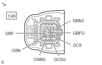
| *a | Front view of wire harness connector
(to Inverter with Converter Assembly) |
Measure the resistance according to the value(s) in the table below.
- Standard Resistance:
Tester Connection Condition Specified Condition C49-8 (GRF) - C49-9 (GRFG) Power switch off 8.9 to 14.8 Ω C49-10 (GSN) - C49-11 (GSNG) Power switch off 22.6 to 34.5 Ω C49-13 (GCS) - C49-12 (GCSG) Power switch off 25.5 to 37.4 Ω
- HINT:
-
To correct the variation of the measured resistance due to temperature, use the following formula to calculate the resistance at 20°C (68°F).
-
R20 = Rt / {1 + 0.00393 X (T - 20)}
-
The calculation is based on the following:
-
R20: Resistance at 20°C (68°F) (mΩ)
-
Rt: Measured resistance (mΩ)
-
T: Temperature when the resistance is measured (°C (°F).)
- Standard Resistance (Check for Short):
Tester Connection Condition Specified Condition C49-8 (GRF) or C49-9 (GRFG) - Body ground and other terminals Power switch off 1 MΩ or higher C49-10 (GSN) or C49-11 (GSNG) - Body ground and other terminals Power switch off 1 MΩ or higher C49-13 (GCS) or C49-12 (GCSG) - Body ground and other terminals Power switch off 1 MΩ or higher C49-7 (DRN3) - Other terminals Power switch off 1 MΩ or higher
Reconnect the C49 inverter with converter assembly connector.
- Result:
Proceed to OK NG
OK
NG
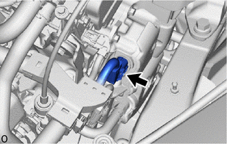
Check the connection condition of the resolver connector and the contact pressure of each terminal. Check the terminals for deformation, and check the connector for water ingress and foreign matter.
- OK:
- The connector is connected securely.
- The terminals are not deformed and are connected securely.
- No water or foreign matter in the connector.
- Result:
Result Proceed to OK A NG (The connector is not connected securely.) B NG (The terminals are not making secure contact or are deformed, or water or foreign matter exists in the connector.) C
A
B
C
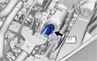
Disconnect the C51 resolver connector.
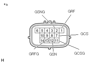
| *a | Component without harness connected
(Generator resolver (Hybrid Vehicle Transaxle Assembly)) |
Measure the resistance according to the value(s) in the table below.
- Standard Resistance:
Tester Connection Condition Specified Condition 1 (GRF) - 8 (GRFG) Power switch off 8.8 to 14.8 Ω 12 (GSN) - 2 (GSNG) Power switch off 22.5 to 34.4 Ω 7 (GCS) - 11 (GCSG) Power switch off 25.5 to 37.3 Ω
- HINT:
-
To correct the variation of the measured resistance due to temperature, use the following formula to calculate the resistance at 20°C (68°F).
-
R20 = Rt / {1 + 0.00393 X (T - 20)}
-
The calculation is based on the following:
-
R20: Resistance at 20°C (68°F) (mΩ)
-
Rt: Measured resistance (mΩ)
-
T: Temperature when the resistance is measured (°C (°F).)
- Standard Resistance (Check for Short):
Tester Connection Condition Specified Condition 1 (GRF) - Body ground and other terminals (except 8 (GRFG)) Power switch off 1 MΩ or higher 8 (GRFG) - Body ground and other terminals (except 1 (GRF)) Power switch off 1 MΩ or higher 12 (GSN) - Body ground and other terminals (except 2 (GSNG)) Power switch off 1 MΩ or higher 2 (GSNG) - Body ground and other terminals (except 12 (GSN)) Power switch off 1 MΩ or higher 7 (GCS) - Body ground and other terminals (except 11 (GCSG)) Power switch off 1 MΩ or higher 11 (GCSG) - Body ground and other terminals (except 7 (GCS)) Power switch off 1 MΩ or higher
Reconnect the C51 resolver connector.
- Result:
Proceed to OK NG
OK
NG