K121F CVT OIL PAN REMOVAL
CAUTION / NOTICE / HINT
The necessary procedures (adjustment, calibration, initialization, or registration) that must be performed after parts are removed, installed, or replaced during the transaxle side cover sub-assembly removal/installation are shown below.
| Replacement Part or Procedure | Necessary Procedure | Effect/Inoperative when not Performed | Link |
|---|---|---|---|
| CVT fluid | ATF thermal degradation estimate reset | The value of the Data List item "ATF Thermal Degradation Estimate" is not estimated correctly | ( 202409,999999,_52,_138817,_0596468,RM100000002NRBH,) 202409,999999,_52,_138817,_0596468,RM100000002NRBH,)
|
| Air bleed oil pump with motor assembly | Stop and start system | (202409,999999,_51,_083056,_0402418,RM100000002NSFT,)
|
- HINT:
-
When the cable is disconnected / reconnected to the auxiliary battery terminal, systems temporarily stop operating. However, each system has a function that completes learning the first time the system is used.
- ·
Learning completes when vehicle is driven
Effect/Inoperative Function When Necessary Procedures are not Performed Necessary Procedures Link Stop and start system Drive the vehicle until stop and start control is permitted (approximately 5 to 60 minutes). ( 202409,999999,_51,_083056,_0402418,RM100000002NSFO,)
Lane tracing assist system Drive the vehicle straight ahead at 15 km/h (10 mph) or more for 1 second or more. ( 201910,999999,_58,_083101,_0401880,RM100000001JE9I,)
Pre-collision system
·Learning completes when vehicle is operated normally
Effect/Inoperative Function When Necessary Procedures are not Performed Necessary Procedures Link *: w/ Power back door system
Power back door function* Fully close the back door by hand.
- HINT:
-
Initialization is not necessary if the above procedures are performed while the back door is closed.
( 202304,999999,_59,_083093,_0584672,RM1000000029PGT,)
Power door lock control system If the back door is locked and therefore cannot be opened, it is necessary to unlock the back door using the door control switch, electrical key transmitter sub-assembly switch. ( 202409,999999,_58,_083092,_0403003,RM100000002NS90,)
Air conditioning system After the ignition switch is turned to ON, the servo motor standard position is recognized -
PROCEDURE

 1.REMOVE BATTERY
53895B
2.REMOVE FRONT FENDER FRONT SPLASH SHIELD RH
53896B
3.REMOVE FRONT FENDER FRONT SPLASH SHIELD LH
51441
4.REMOVE NO. 1 ENGINE UNDER COVER
51420
5.REMOVE NO. 2 ENGINE UNDER COVER ASSEMBLY
53737D
6.REMOVE FRONT FENDER APRON SEAL LH
7.DRAIN CONTINUOUSLY VARIABLE TRANSAXLE FLUID
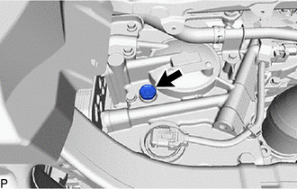
Remove the refill plug and gasket from the rear transaxle case sub-assembly.
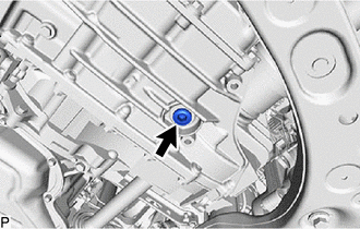
Using a 10 mm hexagon socket wrench, remove the overflow plug and gasket from the transaxle case sub-assembly, and drain the fluid.
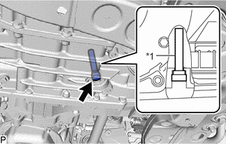
| *1 | Overflow (CVT) Tube |
Using a 6 mm hexagon socket wrench, remove the overflow (CVT) tube from the transaxle case sub-assembly.
- HINT:
-
Removing the overflow (CVT) tube will drain all fluid in the transaxle case sub-assembly.
Using a 6 mm hexagon socket wrench, install the overflow (CVT) tube to the transaxle case sub-assembly.
- Torque:
- 0.8 N*m (8 kgf*cm, 7 in.*lbf)
Using a 10 mm hexagon socket wrench, temporarily install the overflow plug and gasket to the transaxle case sub-assembly.
- HINT:
-
Reuse the old gasket as the overflow plug will be removed again to adjust the fluid level.
Temporarily install the gasket and refill plug to the rear transaxle case sub-assembly.
- HINT:
-
Reuse the old gasket as the refill plug will be removed again to adjust the fluid level.
12601B
8.REMOVE NO. 1 ENGINE COVER SUB-ASSEMBLY
17751
9.REMOVE NO. 1 INLET AIR CLEANER
10.REMOVE AIR CLEANER ASSEMBLY WITH AIR CLEANER HOSE
89661
11.REMOVE ECM
74404B
12.REMOVE BATTERY CLAMP SUB-ASSEMBLY
82121
13.DISCONNECT ENGINE WIRE
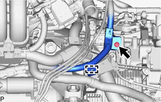
Remove the bolt to disconnect the engine wire from the continuously variable transaxle assembly.
Detach the clamp.

Remove the bolt to disconnect the engine wire from the continuously variable transaxle assembly.
Detach the 3 clamps to disconnect the engine wire from the continuously variable transaxle assembly.
12361
14.REMOVE FRONT ENGINE MOUNTING INSULATOR
16261G
15.DISCONNECT NO. 1 WATER BY-PASS HOSE
32942N
16.REMOVE NO. 1 OIL COOLER OUTLET HOSE
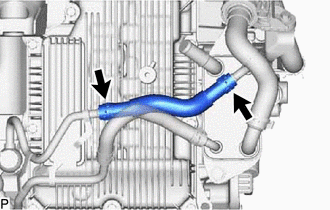
Slide the 2 hose clips and remove the No. 1 oil cooler outlet hose from the transmission oil cooler and oil cooler elbow sub-assembly.
32941R
17.REMOVE OIL COOLER INLET HOSE
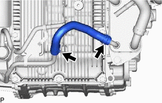
Slide the 2 hose clips and remove the oil cooler inlet hose from the transmission oil cooler and oil cooler elbow sub-assembly.
32901L
18.REMOVE OIL COOLER ELBOW SUB-ASSEMBLY
35015Y
19.REMOVE TRANSAXLE SIDE COVER SUB-ASSEMBLY
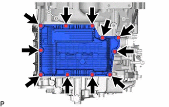
Remove the 11 bolts and transaxle side cover sub-assembly from the transaxle case sub-assembly.
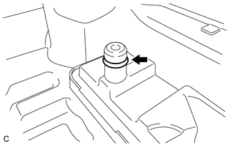
Remove the O-ring from the transaxle side cover sub-assembly.