K121 CVT TRANSMISSION CONTROL CABLE REMOVAL
CAUTION / NOTICE / HINT
The necessary procedures (adjustment, calibration, initialization or registration) that must be performed after parts are removed and installed, or replaced during transmission control cable assembly removal/installation are shown below.
- NOTICE:
-
After the ignition switch is turned off, the navigation system requires approximately a minute to record various types of memory and settings. As a result, after turning the ignition switch off, wait a minute or more before disconnecting the cable from the negative (-) battery terminal.
- HINT:
-
When the cable is disconnected / reconnected to the auxiliary battery terminal, systems temporarily stop operating. However, each system has a function that completes learning the first time the system is used.
- ·
Learning completes when vehicle is driven
Effect/Inoperative Function When Necessary Procedures are not Performed Necessary Procedures Link Stop and start system Drive the vehicle until stop and start control is permitted (approximately 5 to 60 minutes). (  202409,999999,_51,_083056,_0402418,RM100000002NSFO,)
Lane tracing assist system Drive the vehicle straight ahead at 15 km/h (10 mph) or more for 1 second or more. ( 201910,999999,_58,_083101,_0401880,RM100000001JE9I,)
Pre-collision system
·Learning completes when vehicle is operated normally
Effect/Inoperative Function When Necessary Procedures are not Performed Necessary Procedures Link *: w/ Power back door system
Power back door function* Fully close the back door by hand.
- HINT:
-
Initialization is not necessary if the above procedures are performed while the back door is closed.
( 202304,999999,_59,_083093,_0584672,RM1000000029PGT,)
Power door lock control system If the back door is locked and therefore cannot be opened, it is necessary to unlock the back door using the door control switch, electrical key transmitter sub-assembly switch. ( 202409,999999,_58,_083092,_0403003,RM100000002NS90,)
Air conditioning system After the ignition switch is turned to ON, the servo motor standard position is recognized -
PROCEDURE

 1.SECURE VEHICLE
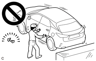
Fully apply the parking brake and chock a wheel.
- CAUTION:
-
- ·
Make sure to apply the parking brake and chock a wheel before performing this procedure.
·If the vehicle is not secure and the shift lever is moved to N, the vehicle may suddenly move, possibly resulting in an accident or serious injury.
2.REMOVE BATTERY
for M20C-FKS:
Click hereGeneral>MAINTENANCE>M20C-FKS BATTERY>REMOVAL202409,999999,_V1,_083136,_0418197,RM100000002NHPI,
for M20D-FKS:
Click hereGeneral>MAINTENANCE>M20D-FKS BATTERY>REMOVAL202409,999999,_V1,_083136,_0403617,RM100000002NHPJ,
89661
3.REMOVE ECM
74404B
4.REMOVE BATTERY CLAMP SUB-ASSEMBLY
53895B
5.REMOVE FRONT FENDER FRONT SPLASH SHIELD RH
53896B
6.REMOVE FRONT FENDER FRONT SPLASH SHIELD LH
51441
7.REMOVE NO. 1 ENGINE UNDER COVER
51420
8.REMOVE NO. 2 ENGINE UNDER COVER ASSEMBLY
58166A
9.REMOVE FRONT FLOOR COVER LH
58810J
10.REMOVE CONSOLE BOX ASSEMBLY
58861B
11.REMOVE NO. 1 CONSOLE BOX DUCT
33820B
12.DISCONNECT TRANSMISSION CONTROL CABLE ASSEMBLY
33820B
13.REMOVE TRANSMISSION CONTROL CABLE ASSEMBLY
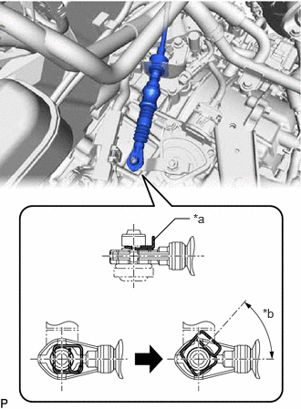
| *a | Clip |
| *b | 45° to 60° |
While disengaging the clip as shown in the illustration, disconnect the transmission control cable assembly from the transmission control shaft lever together with the clip.
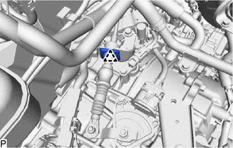
Remove the clip and disconnect the transmission control cable assembly from the No. 1 transmission control cable bracket.
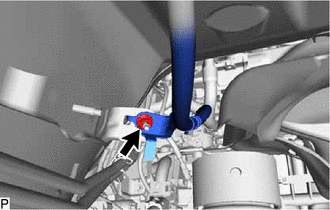
Remove the nut and disconnect the transmission control cable assembly from the vehicle body.
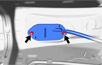
Remove the 2 nuts and then remove the transmission control cable assembly from the vehicle body.