K121 CVT CONTINUOUSLY VARIABLE TRANSAXLE FLUID HIGH TEMPERATURE ADJUSTMENT
CAUTION / NOTICE / HINT
The necessary procedures (adjustment, calibration, initialization, or registration) that must be performed after parts are removed, installed, or replaced during CVT fluid replacement are shown below.
| Replacement Part or Procedure | Necessary Procedure | Effect/Inoperative when not Performed | Link |
|---|---|---|---|
| CVT fluid | ATF thermal degradation estimate reset | The value of the Data List item "ATF Thermal Degradation Estimate" is not estimated correctly | ( 202409,999999,_52,_138176,_0584691,RM100000002NRHB,) 202409,999999,_52,_138176,_0584691,RM100000002NRHB,)
|
| Air bleed oil pump with motor assembly | Stop and Start System | (202409,999999,_51,_083056,_0402418,RM100000002NSFT,)
|
- CAUTION:
- ·
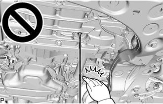
Make sure not to get any of the drained fluid on your hands, etc.
·The high temperature of the drained fluid could cause burns.
·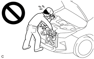
When working near the engine room while the engine has started or the ignition switch is ON, do not touch the rotating components such as the V-ribbed belt or cooling fan.
·Touching the rotating components such as the V-ribbed belt or cooling fan could result in your hand or clothing getting caught and pulled in.
PROCEDURE

 1.ADJUST FLUID LEVEL CVT HIGH TEMPERATURE
Warm up and stop the engine.
Check the fluid temperature.
Connect the GTS to the DLC3 and turn the ignition switch off.
Turn the ignition switch to ON and turn the GTS on.
- NOTICE:
-
To reduce load, make sure that all electrical systems, such as the air conditioning, lighting system, electric fan and audio system are off.
Enter the following menus: Powertrain / Engine / Data List / Engine Speed and A/T Oil Temperature No.1.
- Powertrain > Engine > Data List
-
Tester Display Engine Speed A/T Oil Temperature No.1 - 50003 372 211,180
- NOTICE:
- ·
If the fluid temperature tends to decrease when the fluid temperature is between 85°C (185°F) and 90°C (194°F) with the engine idling, make sure that fluid temperature is above 90°C (194°F) before starting work.
·If the fluid temperature tends to increase when the fluid temperature is between 85°C (185°F) and 90°C (194°F) with the engine idling, make sure that fluid temperature is below 85°C (185°F) before starting work.
·If the fluid temperature tends not to change when the fluid temperature is between 85°C (185°F) and 90°C (194°F) with the engine idling, make sure that fluid temperature is 87.5°C (189.5°F) before starting work.
Depress and hold the brake pedal.
Start the engine.
Slowly move the shift lever from P to D, and then back to P.
- HINT:
- ·
Slowly move the shift lever to circulate the fluid through each part of the continuously variable transaxle assembly.
·Keep the shift lever in each position for approximately 3 seconds.
Lift the vehicle.
- NOTICE:
-
Set the vehicle on a lift so that the vehicle is kept level when it is lifted up (make sure the tilt angle from the front to rear and side to side of the vehicle is within +/- 1°).
Remove the front fender front splash shield RH.
Remove the front fender front splash shield LH.
Remove the No. 1 engine under cover.
Remove the No. 2 engine under cover assembly.
Remove the front fender apron seal LH.
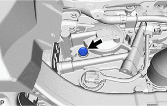
Remove the refill plug and gasket from the rear transaxle case sub-assembly.
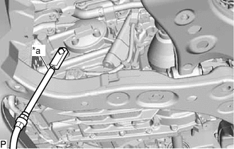
| *a | SST (Filler Plug Adapter) |
Install SST (filler plug adapter) to the refill plug hole.
- SST
- 09993-19025 (09993-10010, 09993-01030)
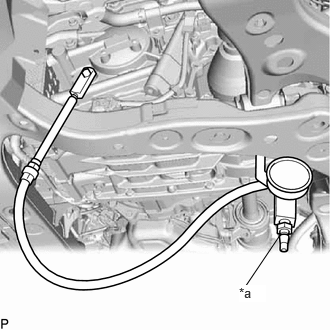
| *a | SST (Vacuum Regulator) |
Connect SST (vacuum regulator) to SST (filler plug adapter).
- SST
- 09993-19025 (09993-10010, 09993-01020)
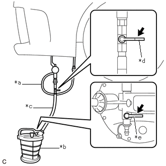
| *a | SST (Vacuum Regulator) |
| *b | SST (Tank Assy) |
| *c | Hose of SST (Tank Assy) |
| *d | Valve Handle (Upper Valve) |
| *e | Valve Handle (Lower Valve) |
Connect the hose of SST (tank assy) to SST (vacuum regulator).
- SST
- 09993-19025 (09993-20010)
- NOTICE:
-
Ensure both of the valves of SST (tank assy) are closed by turning the valve handle (upper valve) and valve handle (lower valve) to the position shown in the illustration so they are perpendicular to the hoses.
Connect a compressed air hose to SST (tank assy).
- NOTICE:
-
Do not apply 689 kPa (7.0 kgf/cm2, 100 psi) or more of compressed air to SST (tank assy).
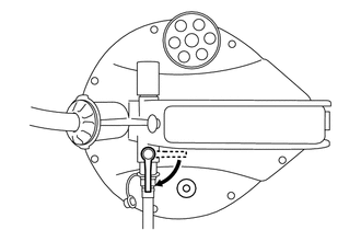
Open the lower valve of SST (tank assy) by turning the valve handle (lower valve) so it is in-line with the compressed air hose.
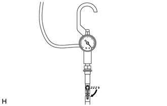
Open the upper valve of SST (tank assy) by turning the valve handle (upper valve) so it is in-line with the hose of SST (tank assy).
- NOTICE:
-
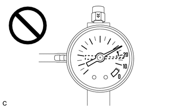
- ·
Make sure to turn the valve handle (upper valve) slowly.
·Make sure the value on the gauge of SST (vacuum regulator) stays between -10 and -20 kPa (-0.1 and -0.2 kgf/cm2, -1.5 and -2.9 psi).
·If the value on the gauge of SST (vacuum regulator) exceeds -20 kPa (-0.2 kgf/cm2, -2.9 psi), make sure to turn the valve handle (upper valve) so it is perpendicular to the hose of SST (tank assy) immediately, otherwise parts inside the continuously variable transaxle assembly may be damaged.
- HINT:
-
Vacuum will be applied to the continuously variable transaxle assembly when both of the valves of SST (tank assy) are opened to prevent fluid loss when removing/installing the overflow plug.
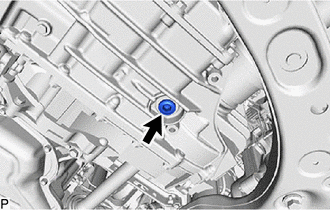
Using a 10 mm hexagon socket wrench, remove the overflow plug and gasket from the transaxle case sub-assembly.
- CAUTION:
-
A small amount of hot fluid may leak from the overflow plug port during removal.
- HINT:
-
Place a container under the overflow plug to collect any fluid that leaks out.
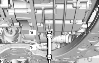
| *a | SST (Adapter 18) |
| *b | SST (Overflow Level Gauge) |
Install SST (adapter 18) to SST (overflow level gauge) and then install SST (overflow level gauge) to the overflow plug hole by hand until it is fully seated against the transaxle case sub-assembly.
- SST
- 09993-01100
09993-19025 (09993-10010, 09993-01010)
- NOTICE:
-
Ensure that the sliding tube of SST (overflow level gauge) is fully retracted into the housing of SST (overflow lever gauge) before inserting it into the overflow plug hole.
- HINT:
-
The level/measurement indicator on SST (overflow level gauge) will read 0 mm (0 in.) when the sliding tube of SST (overflow level gauge) is fully retracted.
Adjust SST (overflow level gauge) to the specified measurement according to the table below and lock the sliding scale of SST (overflow level gauge) by tightening the thumb screw.
- Specified Measurement:
Specified Measurement at Fluid Temperature of 85 to 90°C (185 to 194°F) Engine Idle Speed (rpm) 750 to 850 79.4 to 79.8 mm (3.13 to 3.14 in.)
- NOTICE:
-
Before proceeding with the inspection, make sure the fluid temperature is between 85 to 90°C (185 to 194°F) and the engine idle speed is within the specified range in the table above.
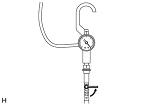
Close the upper valve of SST (tank assy) by turning the valve handle (upper valve) so it is perpendicular to the hose of SST (tank assy).
- NOTICE:
- ·
Make sure to turn the valve handle (upper valve) slowly.
·Make sure that the gauge of SST (vacuum regulator) reads 0 kPa (0 kgf/cm2, 0 psi).
- HINT:
-
Vacuum that was applied to the continuously variable transaxle assembly will not be applied when the valve handle (upper valve) is closed.
Check the fluid flowing from the hose at the bottom of SST (overflow level gauge).
If the amount of fluid that comes out of SST (overflow level gauge) is large, proceed to step [#1].
If no fluid comes out of SST (overflow level gauge), proceed to step [#2].
If the amount of fluid that comes out of SST (overflow level gauge) is large. [#1]
Wait until the fluid flow slows and only drips come out.
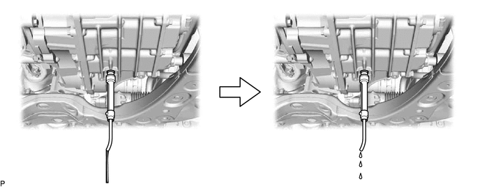
- HINT:
-
The fluid flow will not stop completely because the fluid continues to expand as its temperature increases.
Open the upper valve of SST (tank assy) by turning the valve handle (upper valve) so it is in-line with the hose of SST (tank assy).
- NOTICE:
-
- ·
Make sure to turn the valve handle (upper valve) slowly.
·Make sure the value on the gauge of SST (vacuum regulator) stays between -10 and -20 kPa (-0.1 and -0.2 kgf/cm2, -1.5 and -2.9 psi).
·If the value on the gauge of SST (vacuum regulator) exceeds -20 kPa (-0.2 kgf/cm2, -2.9 psi), make sure to turn the valve handle (upper valve) so it is perpendicular to the hose of SST (tank assy) immediately, otherwise parts inside the continuously variable transaxle assembly may be damaged.
- HINT:
-
Vacuum will be applied to the continuously variable transaxle assembly when both of the valves of SST (tank assy) are opened to prevent fluid loss when removing/installing the overflow plug.
Remove SST (overflow level gauge) from the overflow plug hole.
Coat a new gasket with Toyota Genuine CVT fluid FE and install it to the overflow plug.
Using a 10 mm hexagon socket wrench, install the overflow plug to the transaxle case sub-assembly.
- Torque:
- 49 N*m (500 kgf*cm, 36 ft.*lbf)
- NOTICE:
-
To prevent the gasket from being deformed when tightening, coat it with Toyota Genuine CVT fluid FE.
Close the upper valve of SST (tank assy) by turning the valve handle (upper valve) so it is perpendicular to the hose of SST (tank assy).
- NOTICE:
- ·
Make sure to turn the valve handle (upper valve) slowly.
·Make sure that the gauge of SST (vacuum regulator) reads 0 kPa (0 kgf/cm2, 0 psi).
- HINT:
-
Vacuum that was applied to the continuously variable transaxle assembly will not be applied when the valve handle (upper valve) is closed.
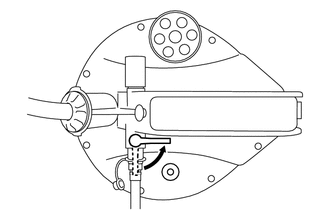
Close the lower valve of SST (tank assy) by turning the valve handle (lower valve) so it is perpendicular to the compressed air hose.
Disconnect the compressed air hose from SST (tank assy).
Disconnect the hose of SST (tank assy) from SST (vacuum regulator).
Disconnect SST (vacuum regulator) from SST (filler plug adapter).
Remove SST (filler plug adapter) from the refill plug hole.
If no fluid comes out of SST (overflow level gauge). [#2]
| *a | SST (Filler Plug Adapter) |
Remove SST (filler plug adapter) from the refill plug hole.
Add fluid through the refill plug hole until fluid comes out of SST (overflow level gauge).
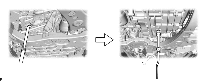
| *a | SST (Overflow Level Gauge) | - | - |
- NOTICE:
-
Use Toyota Genuine CVT fluid FE.
-
Using CVT (Continuously Variable Transaxle) fluid other than the above type may cause abnormal noise or vibration, or damage the CVT (Continuously Variable Transaxle) of your vehicle.
Wait until the fluid flow slows and only drips come out.
- HINT:
-
The fluid flow will not stop completely because the fluid continues to expand as its temperature increases.
| *a | SST (Filler Plug Adapter) |
Install SST (filler plug adapter) to the refill plug hole.
- SST
- 09993-19025 (09993-10010, 09993-01030)
Open the upper valve of SST (tank assy) by turning the valve handle (upper valve) so it is in-line with the hose of SST (tank assy).
- NOTICE:
-
- ·
Make sure to turn the valve handle (upper valve) slowly.
·Make sure the value on the gauge of SST (vacuum regulator) stays between -10 and -20 kPa (-0.1 and -0.2 kgf/cm2, -1.5 and -2.9 psi).
·If the value on the gauge of SST (vacuum regulator) exceeds -20 kPa (-0.2 kgf/cm2, -2.9 psi), make sure to turn the valve handle (upper valve) so it is perpendicular to the hose of SST (tank assy) immediately, otherwise parts inside the continuously variable transaxle assembly may be damaged.
- HINT:
-
Vacuum will be applied to the continuously variable transaxle assembly when both of the valves of SST (tank assy) are opened to prevent fluid loss when removing/installing the overflow plug.
Remove SST (overflow level gauge) from the overflow plug hole.
Coat a new gasket with Toyota Genuine CVT fluid FE and install it to the overflow plug.
Using a 10 mm hexagon socket wrench, install the overflow plug to the transaxle case sub-assembly.
- Torque:
- 49 N*m (500 kgf*cm, 36 ft.*lbf)
- NOTICE:
-
To prevent the gasket from being deformed when tightening, coat it with Toyota Genuine CVT fluid FE.
Close the upper valve of SST (tank assy) by turning the valve handle (upper valve) so it is perpendicular to the hose of SST (tank assy).
- NOTICE:
- ·
Make sure to turn the valve handle (upper valve) slowly.
·Make sure that the gauge of SST (vacuum regulator) reads 0 kPa (0 kgf/cm2, 0 psi).
- HINT:
-
Vacuum that was applied to the continuously variable transaxle assembly will not be applied when the valve handle (upper valve) is closed.
Close the lower valve of SST (tank assy) by turning the valve handle (lower valve) so it is perpendicular to the compressed air hose.
Disconnect the compressed air hose from SST (tank assy).
Disconnect the hose of SST (tank assy) from SST (vacuum regulator).
Disconnect SST (vacuum regulator) from SST (filler plug adapter).
Remove SST (filler plug adapter) from the refill plug hole.
Coat a new gasket with Toyota Genuine CVT fluid FE and install it to the refill plug.
Install the refill plug to the rear transaxle case sub-assembly.
- Torque:
- 49 N*m (500 kgf*cm, 36 ft.*lbf)
Lower the vehicle.
Disconnect the GTS from the DLC3.
Lift the vehicle.
Clean each part.
Check for fluid leaks.
Install the front fender apron seal LH.
Install the No. 2 engine under cover assembly.
Install the No. 1 engine under cover.
Install the front fender front splash shield LH.
Install the front fender front splash shield RH.
Lower the vehicle.