DOOR / HATCH FRONT DOOR DISASSEMBLY
CAUTION / NOTICE / HINT
The necessary procedures (adjustment, calibration, initialization, or registration) that must be performed after parts are removed and installed, or replaced during front door disassembly/reassembly are shown below.
| Replaced Part or Performed Procedure | Effect/Inoperative Function When Necessary Procedures are not Performed | Necessary Procedures | Link |
|---|---|---|---|
·
Outer rear view mirror assembly LH (Including removal and installation) ·
Outer rear view mirror assembly RH (Including removal and installation) |
Panoramic view monitor system | Side television camera view adjustment | ( 202304,999999,_56,_083082,_0586733,RM1000000029R9F,) 202304,999999,_56,_083082,_0586733,RM1000000029R9F,)
|
·
Side television camera assembly LH or outer rear view mirror assembly LH ·
Side television camera assembly RH or outer rear view mirror assembly RH |
Panoramic view monitor system | Television camera view adjustment (Adjustment of all cameras)
|
(202304,999999,_56,_083082,_0586733,RM1000000029R9F,)
|
·
Power window regulator motor assembly LH ·
Power window regulator motor assembly RH ·
Front door window regulator sub-assembly LH ·
Front door window regulator sub-assembly RH ·
Front door glass sub-assembly LH ·
Front door glass sub-assembly RH ·
Front door glass run LH ·
Front door glass run RH |
·
Auto up and down function ·
Jam protection function ·
Catch protection function ·
Remote control function ·
Wireless transmitter-linked function ·
Key-linked function ·
Key-off operation function ·
Window open warning function |
Initialize power window control system | (202409,999999,_59,_083107,_0400960,RM100000002NUSM,)
|
- HINT:
-
When the cable is disconnected / reconnected to the auxiliary battery terminal, systems temporarily stop operating. However, each system has a function that completes learning the first time the system is used.
- ·
Learning completes when vehicle is driven
Effect/Inoperative Function When Necessary Procedures are not Performed Necessary Procedures Link Lane tracing assist system Drive the vehicle straight ahead at 35 km/h (22 mph) or more for 5 second or more. ( 201910,999999,_58,_083101,_0401880,RM100000001JE9I,)
Pre-collision system
- ·
Learning completes when vehicle is operated normally
Effect/Inoperative Function When Necessary Procedures are not Performed Necessary Procedures Link Power back door function Fully close the back door by hand.
- HINT:
-
Initialization is not necessary if the above procedures are performed while the back door is closed.
( 202304,999999,_59,_083093,_0584672,RM1000000029PGT,)
Power door lock control system If the back door is locked and therefore cannot be opened, it is necessary to unlock the back door using the door control switch, electrical key transmitter sub-assembly switch. ( 202409,999999,_58,_083092,_0403003,RM100000002NS90,)
Air conditioning system After the ignition switch is turned to ON, the servo motor standard position is recognized -
| Replaced Part or Performed Procedure | Effect/Inoperative Function when Necessary Procedures are not Performed | Necessary Procedures | Link |
|---|---|---|---|
·
Outer rear view mirror assembly LH (Including removal and installation) ·
Outer rear view mirror assembly RH (Including removal and installation) |
Panoramic view monitor system | Side television camera view adjustment | (202304,999999,_56,_083082,_0586733,RM1000000029R9F,)
|
·
Side television camera assembly LH or outer rear view mirror assembly LH ·
Side television camera assembly RH or outer rear view mirror assembly RH |
Panoramic view monitor system | Television camera view adjustment (Adjustment of all cameras)
|
(202304,999999,_56,_083082,_0586733,RM1000000029R9F,)
|
·
Power window regulator motor assembly LH ·
Power window regulator motor assembly RH ·
Front door window regulator sub-assembly LH ·
Front door window regulator sub-assembly RH ·
Front door glass sub-assembly LH ·
Front door glass sub-assembly RH ·
Front door glass run LH ·
Front door glass run RH |
·
Auto up and down function ·
Jam protection function ·
Catch protection function ·
Remote control function ·
Wireless transmitter-linked function ·
Key-linked function ·
Key-off operation function ·
Window open warning function |
Initialize power window control system | (202409,999999,_59,_083107,_0400960,RM100000002NUSM,)
|
- HINT:
-
When the cable is disconnected / reconnected to the auxiliary battery terminal, systems temporarily stop operating. However, each system has a function that completes learning the first time the system is used.
- ·
Learning completes when vehicle is driven
Effect/Inoperative Function When Necessary Procedures are not Performed Necessary Procedures Link Stop and start system Drive the vehicle until stop and start control is permitted (approximately 5 to 60 minutes). ( 202409,999999,_51,_083056,_0402418,RM100000002NSFO,)
Lane tracing assist system Drive the vehicle straight ahead at 15 km/h (10 mph) or more for 1 second or more. ( 201910,999999,_58,_083101,_0401880,RM100000001JE9I,)
Pre-collision system
- ·
Learning completes when vehicle is operated normally
Effect/Inoperative Function When Necessary Procedures are not Performed Necessary Procedures Link *: w/ Power back door system
Power back door function* Fully close the back door by hand.
- HINT:
-
Initialization is not necessary if the above procedures are performed while the back door is closed.
( 202304,999999,_59,_083093,_0584672,RM1000000029PGT,)
Power door lock control system If the back door is locked and therefore cannot be opened, it is necessary to unlock the back door using the door control switch, electrical key transmitter sub-assembly switch. ( 202409,999999,_58,_083092,_0403003,RM100000002NS90,)
Air conditioning system After the ignition switch is turned to ON, the servo motor standard position is recognized -
·Use the same procedure for the RH and LH sides.
·The procedure below is for the LH side.
·Before performing disassembly work on the front door, make sure that the front door glass is fully open and be sure to disconnect the cable from the auxiliary negative (-) battery terminal.
PROCEDURE

 1. PRECAUTION
- CAUTION:
-
-
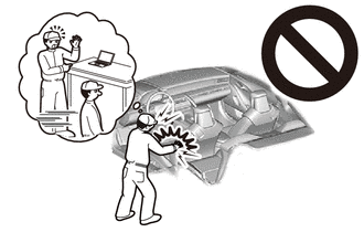
Be sure to read Precaution thoroughly before servicing.
- ·
- NOTICE:
-
After turning the ignition switch off, waiting time may be required before disconnecting the cable from the auxiliary negative (-) battery terminal.
2.DISCONNECT CABLE FROM NEGATIVE AUXILIARY BATTERY TERMINAL
- CAUTION:
-
- ·
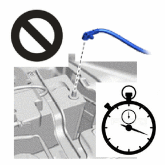
Wait at least 60 seconds after disconnecting the cable from the negative (-) auxiliary battery terminal to disable the SRS system.
·If the airbag deploys for any reason, it may cause a serious accident.
for M20C-FKS:
Click hereGeneral>MAINTENANCE>M20C-FKS BATTERY>REMOVAL202409,999999,_V1,_083136,_0418197,RM100000002NHPI,
for M20D-FKS:
Click hereGeneral>MAINTENANCE>M20D-FKS BATTERY>REMOVAL202409,999999,_V1,_083136,_0403617,RM100000002NHPJ,
69278B
3.REMOVE FRONT DOOR INSIDE HANDLE BEZEL LH
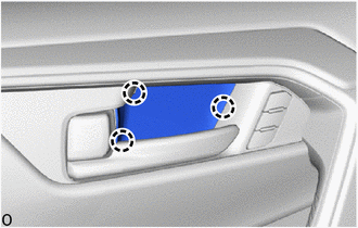
Detach the claw and remove the front door inside handle bezel LH.
74640C
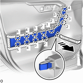
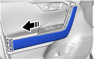
4.REMOVE DOOR ASSIST GRIP ASSEMBLY LH
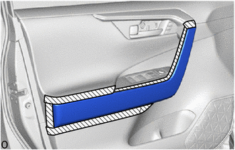

|
Protective Tape |
Apply protective tape to the front door trim board sub-assembly LH as shown in the illustration.

|
Remove in this Direction |
Using a moulding remover A, detach the clip.
Detach the claw in the order shown in the illustration.
|
|
Remove in this Direction |
Detach the guide in the direction indicated by the arrow shown in the illustration and remove the door assist grip assembly LH.
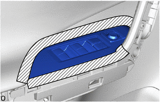
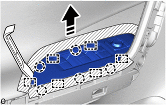
5.REMOVE MULTIPLEX NETWORK MASTER SWITCH ASSEMBLY WITH FRONT DOOR ARMREST BASE PANEL (for Driver Side)
|
|
Protective Tape |
Apply protective tape around the multiplex network master switch assembly with front door armrest base panel.
|
|
Remove in this Direction |
Using a moulding remover A, detach the guide and claw as shown in the illustration.
|
|
Remove in this Direction |
Detach the guide in the direction indicated by the arrow shown in the illustration and remove the multiplex network master switch assembly with front door armrest base panel.
Disconnect the 2 connectors.
84040
6.REMOVE MULTIPLEX NETWORK MASTER SWITCH ASSEMBLY (for Driver Side)
84870A
7.REMOVE OUTER MIRROR SWITCH ASSEMBLY (for Driver Side)
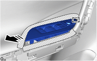
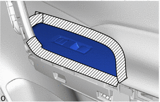
8.REMOVE POWER WINDOW REGULATOR SWITCH ASSEMBLY WITH FRONT DOOR ARMREST BASE PANEL (for Front Passenger Side)
|
|
Protective Tape |
Apply protective tape around the power window regulator switch assembly with front door armrest base panel.
|
|
Remove in this Direction |
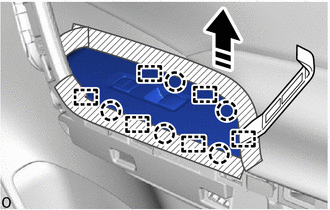
Using a moulding remover A, detach the guide and claw as shown in the illustration.
|
|
Remove in this Direction |
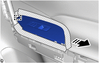
Detach the guide in the direction indicated by the arrow shown in the illustration and remove the power window regulator switch assembly with front door armrest base panel.
Disconnect the connector.
84810
9.REMOVE POWER WINDOW REGULATOR SWITCH ASSEMBLY (for Front Passenger Side)
67602
10.REMOVE FRONT DOOR TRIM BOARD SUB-ASSEMBLY LH
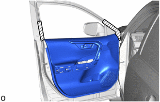
|
|
Protective Tape |
Apply protective tape to the front door panel as shown in the illustration.
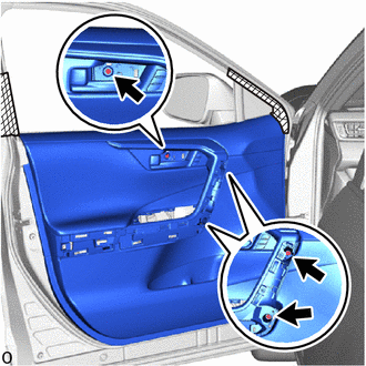
Remove the 3 screws.
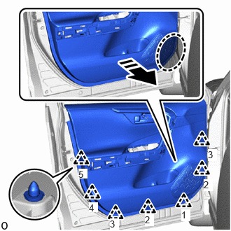

|
Place Hand Here |
|
|
Remove in this Direction |
Place your hand at the position shown in the illustration, and while pulling the front door trim board sub-assembly LH toward you, detach the clip and disconnect the front door trim board sub-assembly LH from the front door panel.
- HINT:
- ·
Detach the clip in the order shown in the illustration.
·Securely detach the clips one by one.
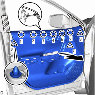
|
|
Remove in this Direction |
Pull the front door trim board sub-assembly LH in the direction indicated by the arrow shown in the illustration to detach the claw and clip to remove the front door trim board sub-assembly LH.
- HINT:
-
Detach the claw and clip in the order shown in the illustration.
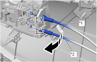
| *1 | Front Door Inside Locking Cable Assembly |
| *2 | Front Door Lock Remote Control Cable Assembly |
|
|
Remove in this Direction |
Detach the clamp and disconnect the front door lock remote control cable assembly and front door inside locking cable assembly as shown in the illustration.
69206B
11.REMOVE FRONT DOOR INSIDE HANDLE SUB-ASSEMBLY LH
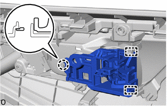
Detach the clamp and claw.
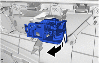
|
|
Remove in this Direction |
Remove the front door inside handle sub-assembly LH in the direction indicated by the arrow as shown in the illustration.
68172A
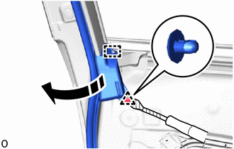
12.REMOVE FRONT DOOR INNER GLASS WEATHERSTRIP LH
|
|
Remove in this Direction |
|
|
Protective Tape |
Using a clip remover with its tip wrapped with protective tape, detach the clip.
Detach the guide and roll up the front door weatherstrip LH enough that the front door inner glass weatherstrip LH can be removed.
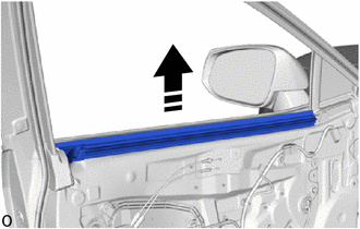
|
|
Remove in this Direction |
Remove the front door inner glass weatherstrip LH with front door rear belt seal LH as shown in the illustration.
68195B
13.REMOVE FRONT DOOR REAR BELT SEAL LH
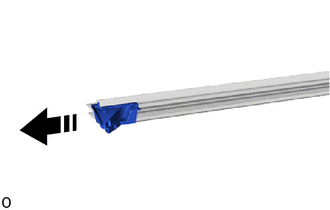
|
|
Remove in this Direction |
Remove the front door rear belt seal LH from the front door inner glass weatherstrip LH as shown in the illustration.
68193C
14.REMOVE FRONT DOOR FRONT BELT SEAL LH
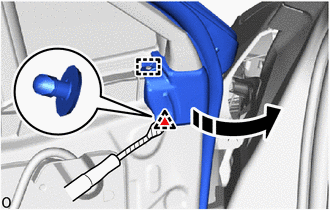
|
|
Remove in this Direction |
|
|
Protective Tape |
Using a clip remover with its tip wrapped with protective tape, detach the clip.
Detach the guide and roll up the front door weatherstrip LH enough that the front door front belt seal LH can be removed.
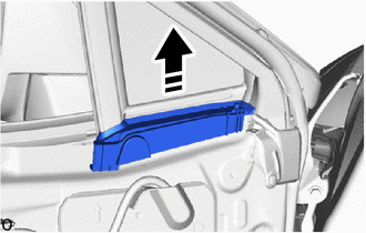
|
|
Remove in this Direction |
Remove the front door front belt seal LH as shown in the illustration.
87964
15.REMOVE OUTER MIRROR INSTALL HOLE COVER LH
87940
16.REMOVE OUTER REAR VIEW MIRROR ASSEMBLY LH
86160
17.REMOVE FRONT NO. 1 SPEAKER ASSEMBLY
67832
18.REMOVE FRONT DOOR SERVICE HOLE COVER LH
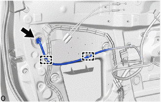
Disconnect the connector.
Detach the clamp.
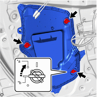
| *a | Location Mark |
| *b | Bead Mark |
|
|
Turn in this Direction |

|
Service Hole Cover Clip |
Check that the service hole cover clip knob and bead mark are aligned.
Turn the service hole cover clip 45° clockwise to the location mark and then remove the service hole cover clip.
- HINT:
-
Use the same procedure for the other service hole cover clips.
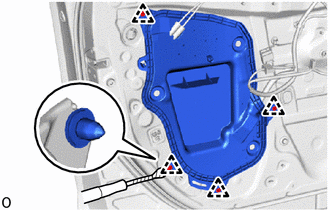
|
|
Protective Tape |
Using a clip remover with its tip wrapped with protective tape, detach the clip.
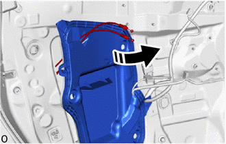
|
|
Remove in this Direction |
Pull out the front door lock remote control cable assembly LH and front door inside locking cable assembly LH from the front door service hole cover LH.
89835
19.REMOVE DOOR SIDE AIRBAG SENSOR LH
68102
20.REMOVE FRONT DOOR GLASS SUB-ASSEMBLY LH
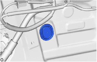
Remove the hole plug.
for Driver Side:
Connect the multiplex network master switch assembly connector.
for Front Passenger Side:
Connect the power window regulator switch assembly connector.
Connect the cable to the negative (-) auxiliary battery terminal.
Turn the ignition switch to ON.
Move the front door glass sub-assembly LH until the installation bolts can be seen.
Turn the ignition switch off.
Disconnect the cable from the negative (-) auxiliary battery terminal.
- CAUTION:
-
- ·
Wait at least 60 seconds after disconnecting the cable from the negative (-) auxiliary battery terminal to disable the SRS system.
·If the airbag deploys for any reason, it may cause a serious accident.
for Driver Side:
Disconnect the multiplex network master switch assembly connector.
for Front Passenger Side:
Disconnect the power window regulator switch assembly connector.
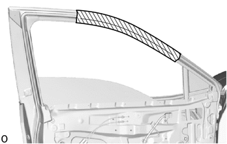
|
|
Protective Tape |
Apply protective tape around the front door panel as shown in the illustration.
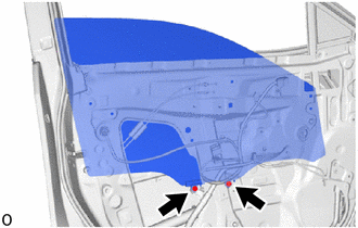
Remove the 2 bolts.
- NOTICE:
-
After the bolts are removed, do not allow the front door glass sub-assembly LH to fall.
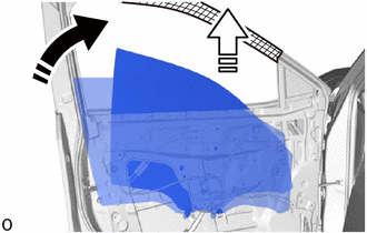
|
|
Remove in this Direction (1) |

|
Remove in this Direction (2) |
Remove the front door glass sub-assembly LH in the direction indicated by the arrows, in the order shown in the illustration.
- NOTICE:
-
Be careful not to damage the front door glass sub-assembly LH.
67664C
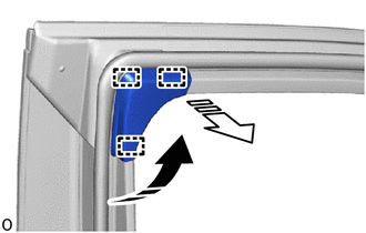
21.REMOVE DOOR FRAME GARNISH LH
|
|
Remove in this Direction (1) |
|
|
Remove in this Direction (2) |
Detach the guide and remove the door frame garnish LH in the direction indicated by the arrows, in the order shown in the illustration.
68151E
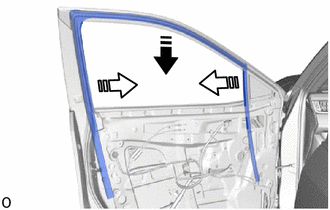
22.REMOVE FRONT DOOR GLASS RUN LH
|
|
Remove in this Direction (1) |
|
|
Remove in this Direction (2) |
Remove the front door glass run LH as shown in the illustration.
69802
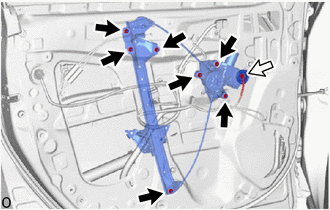
23.REMOVE FRONT DOOR WINDOW REGULATOR SUB-ASSEMBLY LH
|
|
Nut |

|
Connector |
Disconnect the connector.
Remove the 7 nuts and the front door window regulator sub-assembly LH.
- NOTICE:
-
Do not damage the front door panel with the front door window regulator sub-assembly LH.
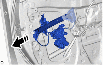
- HINT:
-
 0,0 0,0 false
Remove in this Direction
-
When removing the front door window regulator assembly LH, pull it out from the service hole as shown in the illustration.
85720C
24.REMOVE POWER WINDOW REGULATOR MOTOR ASSEMBLY LH
67404F
25.REMOVE FRONT DOOR REAR LOWER FRAME SUB-ASSEMBLY LH
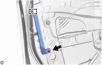
Remove the bolt.
Detach the guide and remove the front door rear lower frame sub-assembly LH.
67402F
26.REMOVE FRONT DOOR FRONT LOWER FRAME SUB-ASSEMBLY LH
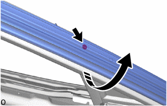
|
|
Lift up in this Direction |
Lift up the front door weatherstrip LH as shown in the illustration.
Remove the screw.
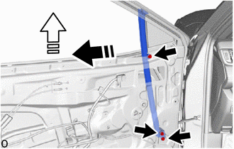
|
|
Remove in this Direction (1) |
|
|
Remove in this Direction (2) |
Remove the 3 bolts.
Remove the front door front lower frame sub-assembly LH in the direction indicated by the arrows, in the order shown in the illustration.
68126
27.REMOVE FRONT DOOR FIX WINDOW GLASS LH
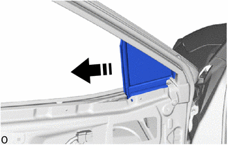
|
|
Remove in this Direction |
Remove the front door fix window glass LH as shown in the illustration.
75720
28.REMOVE FRONT DOOR BELT MOULDING ASSEMBLY LH
69220
29.REMOVE FRONT DOOR OUTSIDE HANDLE ASSEMBLY LH
|
|
Remove in this Direction |
|
|
Protective Tape |
w/ Entry and Start System:
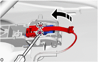
Using a screwdriver with its tip wrapped with protective tape, detach the claw and open the connector cover as shown in the illustration.
|
|
Protective Tape |
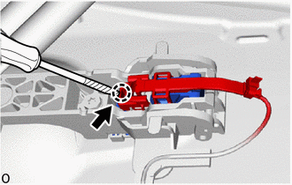
Using a screwdriver with its tip wrapped with protective tape, detach the claw to disconnect the connector and connector cover as shown in the illustration.
| *1 | Holder |
|
|
Remove in this Direction |
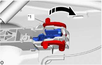
Detach the holder as shown in the illustration.
|
|
Remove in this Direction |
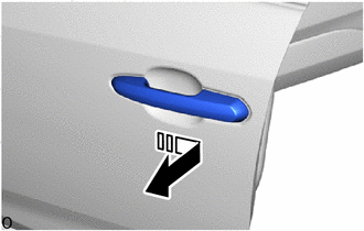
Remove the front door outside handle assembly LH by sliding and pulling it in the direction indicated by the arrow in the illustration.
30.REMOVE FRONT DOOR LOCK CYLINDER ASSEMBLY LH (for Driver Side)
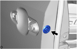
Remove the hole plug.

Using a T30 "TORX" socket wrench, loosen the "TORX" screw.
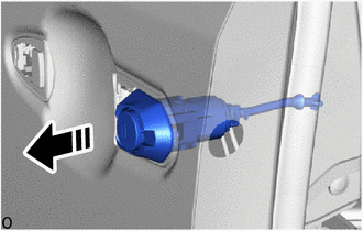
|
|
Remove in this Direction |
Remove the front door lock cylinder assembly LH as shown in the illustration.
69217D
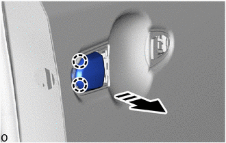
31.REMOVE FRONT DOOR OUTSIDE HANDLE COVER (for Front Passenger Side)
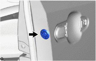
Remove the hole plug.
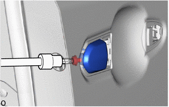
Using a T30 "TORX" socket wrench, loosen the "TORX" screw.
|
|
Remove in this Direction |
Detach the claw and remove the front door outside handle cover as shown in the illustration.
69241H
32.REMOVE FRONT DOOR FRONT OUTSIDE HANDLE PAD
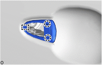
Detach the claw and guide to remove the front door front outside handle pad.
69242F
33.REMOVE FRONT DOOR REAR OUTSIDE HANDLE PAD
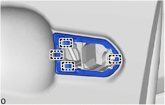
Detach the guide and remove the front door rear outside handle pad.
69312
34.REMOVE FRONT DOOR LOCK OPEN ROD LH
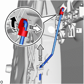
| *1 | Snap |
|
|
Remove in this Direction (1) |
|
|
Remove in this Direction (2) |

|
Remove in this Direction (3) |
Detach the snap as shown in the illustration.
Remove the front door lock open rod LH in the direction indicated by the arrow shown in the illustration.
69202A
35.REMOVE FRONT DOOR OUTSIDE HANDLE FRAME SUB-ASSEMBLY LH
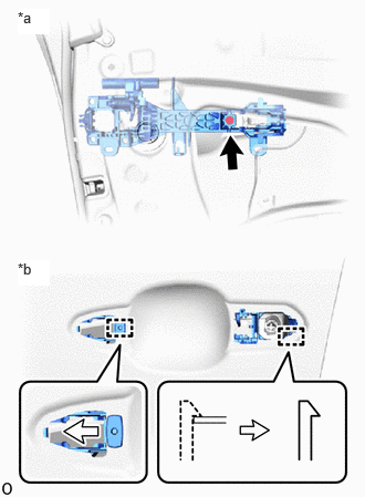
| *a | Inside |
| *b | Outside |
Using a T30 "TORX" socket wrench, loosen the "TORX" screw.
Detach the guide and remove the front door outside handle frame sub-assembly LH.
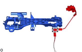
w/ Entry and Start System:
Detach the wire harness clamp.
69040A
36.REMOVE FRONT DOOR LOCK WITH MOTOR ASSEMBLY LH
69318C
37.REMOVE DOOR LOCK WIRING HARNESS SEAL
When reusing front door lock with motor assembly LH:
69036A
38.REMOVE FRONT DOOR LOCK COVER SUB-ASSEMBLY LH
69720D
39.REMOVE FRONT DOOR LOCK REMOTE CONTROL CABLE ASSEMBLY
69760B
40.REMOVE FRONT DOOR INSIDE LOCKING CABLE ASSEMBLY
68610
41.REMOVE FRONT DOOR CHECK ASSEMBLY
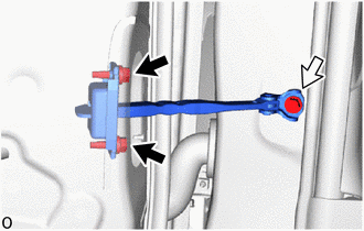
|
|
Bolt (A) |
|
|
Bolt (B) |
Remove the 2 bolts (A), bolt (B) and front door check assembly.
67862
42.REMOVE FRONT DOOR WEATHERSTRIP LH
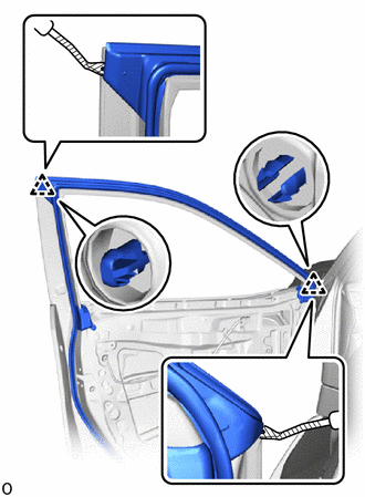
|
|
Protective Tape |
Using a clip remover with its tip wrapped with protective tape, detach the clip.
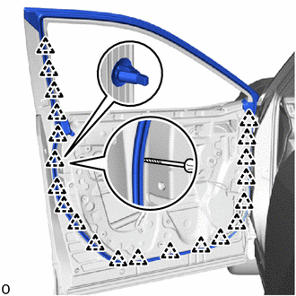
|
|
Protective Tape |
Using a screwdriver with its tip wrapped with protective tape, detach the clip and remove the front door weatherstrip LH.
75756D
43.REMOVE FRONT DOOR WINDOW FRAME MOULDING LH (CENTER PILLAR SIDE)
67856D
44.REMOVE FRONT DOOR PANEL PROTECTOR LH
75792
45.REMOVE DOOR WINDOW FRAME MOULDING CLIP
- HINT:
-
Perform the following procedure only when replacement of a door window frame moulding clip in necessary.
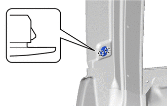
Detach the claw and remove the door window frame moulding clip.
75754A
46.REMOVE FRONT DOOR UPPER WINDOW FRAME MOULDING LH
67864B
47.REMOVE FRONT DOOR NO. 2 WEATHERSTRIP LH
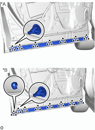
| *A | for Type A |
| *B | for Type B |
Using a screwdriver with its tip wrapped with protective tape, detach the clip and remove the front door No. 2 weatherstrip LH.
75074
48.REMOVE FRONT DOOR LOWER OUTSIDE MOULDING SUB-ASSEMBLY LH
49.REMOVE SCREW GROMMET
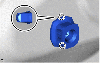
Detach the claw and remove the screw grommet.
- HINT:
-
Use the same procedure described for the other side.
50.REMOVE HOLE PLUG
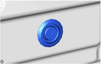
Remove the hole plug.
- HINT:
-
Use the same procedure described for the other side.
67001A
51.REMOVE FRONT DOOR PANEL CUSHION
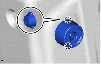
Detach the claw and remove the front door panel cushion.
- HINT:
-
Use the same procedure described for the other side.