SLIDING ROOF / CONVERTIBLE SLIDING ROOF HOUSING(for Moon Roof) INSTALLATION
PROCEDURE

 63203F
1.INSTALL SLIDING ROOF HOUSING SUB-ASSEMBLY
63203F
1.INSTALL SLIDING ROOF HOUSING SUB-ASSEMBLY
Temporarily install the sliding roof housing sub-assembly with the 6 nuts and 4 bolts.
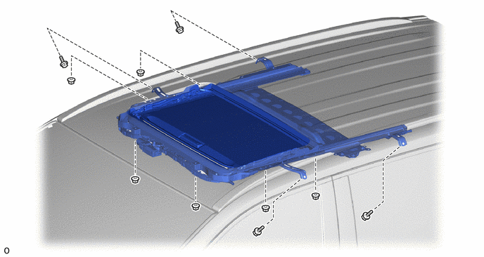
Tighten the 6 nuts and 4 bolts.
- Torque:
- Bolt : 8.0 N*m (82 kgf*cm, 71 in.*lbf)
- Nut : 8.0 N*m (82 kgf*cm, 71 in.*lbf)
- NOTICE:
-

-
If the removed nut is the same shape as that shown in the illustration, replace it with the supplied replacement part.
2.CONNECT SLIDING ROOF DRAIN HOSE
Connect the sliding roof drain hose.
- HINT:
-
Slide the hose to the base of the drain pipe.
for Front Side:
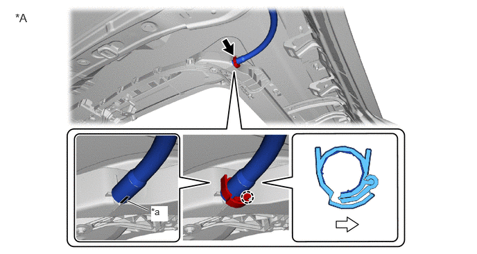
| *A | for Front Side | - | - |
| *a | Marking | - | - |

|
Sliding Roof Drain Hose Clamp | 
|
Rear Side |
- HINT:
-
Use the same procedure for the other side.
for Rear Side:
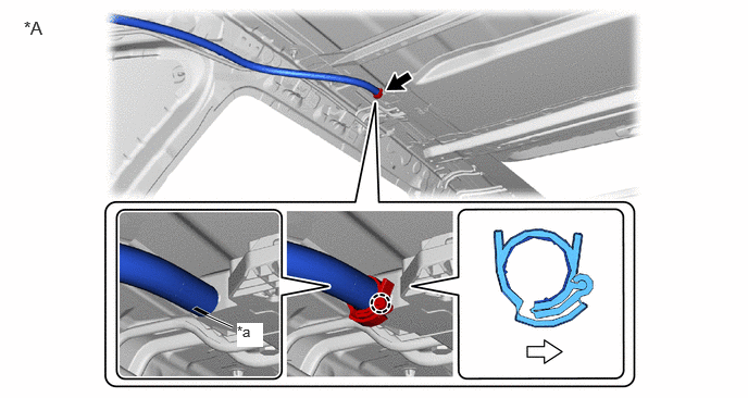
| *A | for Rear Side | - | - |
| *a | Marking | - | - |
|
|
Sliding Roof Drain Hose Clamp |
|
Inside |
- HINT:
-
Use the same procedure for the other side.
Attach the claw to secure the sliding roof drain hose.
- HINT:
-
Make sure that the sliding roof drain hose clamp is on the marking or between the marking and hose end.
62180A
3.INSTALL CURTAIN SHIELD AIRBAG ASSEMBLY LH
62170A
4.INSTALL CURTAIN SHIELD AIRBAG ASSEMBLY RH
- HINT:
-
Use the same procedure described for the LH side.
63201P
5.INSTALL SLIDING ROOF GLASS SUB-ASSEMBLY
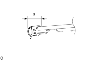
Measure the width (a) of the sliding roof weatherstrip.
- HINT:
-
This measurement will be used in a later step.
Using a T25 "TORX" socket wrench, temporarily install the sliding roof panel sub-assembly with the 4 screws.
Perform a level check.
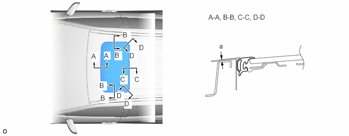
Check the difference in level "a" between the roof panel and the upper surface of the sliding roof weatherstrip when the sliding roof panel sub-assembly is fully closed.
- HINT:
-
"+" represents the condition that the glass is above the panel level. "-" represents the condition that the glass is below the panel level.
- Standard:
Area Measurement Area Measurement A-A (a) 0 + 1.0 mm (0 + 0.0394 in.)
0 - 2.0 mm (0 - 0.0787 in.)B-B (a) 0 + 1.5 mm (0 + 0.0591 in.)
0 - 1.5 mm (0 - 0.0591 in.)C-C (a) 0 + 2.0 mm (0 + 0.0787 in.)
0 - 1.0 mm (0 - 0.0394 in.)D-D (a) 0 + 1.5 mm (0 + 0.0591 in.)
0 - 1.0 mm (0 - 0.0394 in.)
Check the deformation of the sliding roof weatherstrip.
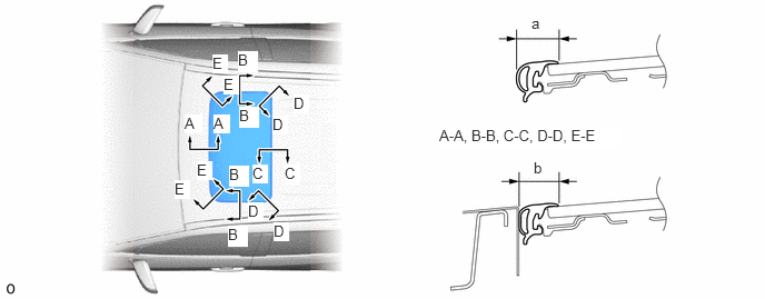
With the sliding roof panel sub-assembly in the fully closed position, measure the width (b) of the sliding roof weatherstrip and, using the width (a) measured in step a., calculate the deformation of the sliding roof weatherstrip (a - b).
- Standard:
Area Measurement Area Measurement A-A (a - b) 0.5 mm (0.0197 in.) to 2.5 mm (0.0984 in.) B-B (a - b) 0.5 mm (0.0197 in.) to 2.5 mm (0.0984 in.) C-C (a - b) 0.5 mm (0.0197 in.) to 2.5 mm (0.0984 in.) D-D (a - b) 0.8 mm (0.0315 in.) to 2.8 mm (0.110 in.) E-E (a - b) 0.8 mm (0.0315 in.) to 2.8 mm (0.110 in.) - -
After adjusting the sliding roof panel sub-assembly, using a T25 "TORX" socket wrench, install the sliding roof panel sub-assembly with the 4 "TORX" screws.
- Torque:
- 4.0 N*m (41 kgf*cm, 35 in.*lbf)
6. CHECK FOR WATER LEAK
After adjusting the sliding roof panel sub-assembly, check for water leakage into the vehicle interior.
If there are any leaks, readjust the sliding roof panel sub-assembly.
63218S
7.INSTALL SLIDING ROOF SIDE GARNISH LH
Attach the 3 claws and guide to install the sliding roof side garnish LH.
63217R
8.INSTALL SLIDING ROOF SIDE GARNISH RH
- HINT:
-
Use the same procedure described for the LH side.
9.CONNECT CABLE TO NEGATIVE AUXILIARY BATTERY TERMINAL
10. INITIALIZATION AFTER RECONNECTING AUXILIARY BATTERY TERMINAL
- HINT:
-
When disconnecting and reconnecting the auxiliary battery, there is an automatic learning function that completes learning when the respective system is used.
11. PERFORM DIAGNOSTIC SYSTEM CHECK
12.CHECK SRS WARNING LIGHT
13.PERFORM SYSTEM INITIALIZATION AND CALIBRATION
14.INITIALIZE SLIDING ROOF SYSTEM
15.CHECK SLIDING ROOF SYSTEM