METER / GAUGE / DISPLAY METER / GAUGE SYSTEM(for SFTM Made) Fuel Lid Opener System Operation Message Display Malfunction
DESCRIPTION
The combination meter assembly and ECM are connected via direct line. The combination meter assembly displays fuel lid opener system operation messages according to the fuel lid signals received from the ECM.
WIRING DIAGRAM
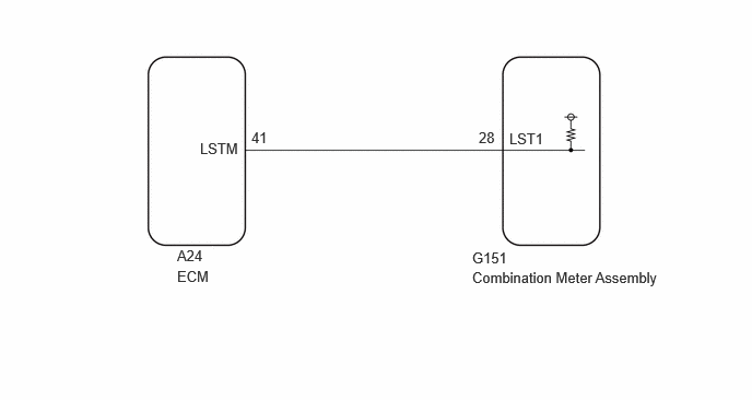
CAUTION / NOTICE / HINT
- NOTICE:
- ·
When replacing the combination meter assembly, always replace it with a new one. If a combination meter assembly which was installed to another vehicle is used, the information stored in it will not match the information from the vehicle and a DTC may be stored.
·The following troubleshooting procedure is based on the assumption that the SFI system and fuel lid opener system are normal. Confirm that the SFI system and fuel lid opener system are not malfunctioning before performing the following procedure.
PROCEDURE
Disconnect the A24 ECM connector.
Measure the voltage according to the value(s) in the table below.
- Standard Voltage:
Tester Connection Switch Condition Specified Condition A24-41 (LSTM) - Body ground Ignition switch off 11 to 14 V
- Result:
Proceed to OK NG
OK
NG
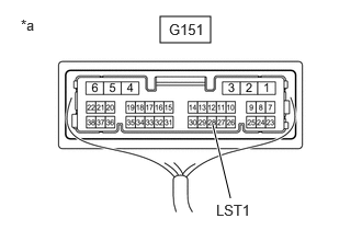
| *a | Component with harness connected
(Combination Meter Assembly) |
Connect the ECM connector.
Operate the fuel lid opener switch.
Check the signal waveform according to the condition(s) in the table below.
- NOTICE:
-
Perform the inspection from the back of the connector with the connector connected.
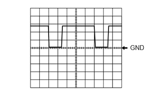
Waveform 1:
| Item | Condition |
|---|---|
| Tester connection | G151-28 (LST1) - Body ground |
| Tool setting | 5 V/DIV., 20 ms./DIV. |
| Vehicle condition | "Close Fuel Lid" displayed on multi-information display |
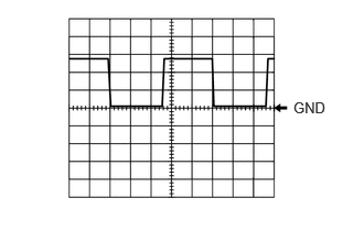
Waveform 2:
| Item | Condition |
|---|---|
| Tester connection | G151-28 (LST1) - Body ground |
| Tool setting | 5 V/DIV., 20 ms./DIV. |
| Vehicle condition | "Ready to Refuel" displayed on multi-information display |
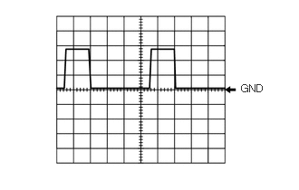
Waveform 3:
| Item | Condition |
|---|---|
| Tester connection | G151-28 (LST1) - Body ground |
| Tool setting | 5 V/DIV., 20 ms./DIV. |
| Vehicle condition | "Please Wait Fuel Door Opening" displayed on multi-information display |
- Result:
Result Proceed to All of the waveforms are output normally A A waveform is not output normally B
A
B
Disconnect the A24 ECM connector.
Disconnect the G151 combination meter assembly connector.
Measure the resistance according to the value(s) in the table below.
- Standard Resistance:
Tester Connection Condition Specified Condition G151-28 (LST1) - A24-41 (LSTM) Always Below 1 Ω G151-28 (LST1) or A24-41 (LSTM) - Body ground Always 10 kΩ or higher
- Result:
Proceed to OK NG
OK
NG