AUDIO / VIDEO AUDIO AND VISUAL SYSTEM Even though Headlights are Turned on Head-unit does not Dim the Display
WIRING DIAGRAM
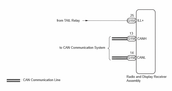
CAUTION / NOTICE / HINT
- NOTICE:
-
Depending on the parts that are replaced during vehicle inspection or maintenance, performing initialization, registration or calibration may be needed.
PROCEDURE
Select settings icon from the screen.
Turn the light control switch to the tail or head position.
Check that the "Automatic" setting on the display adjustment screen is set to on.
- Result:
Result Proceed to "Automatic" setting is set to on. A "Automatic" setting is set to off. B
A
B
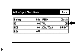
Select "Function Check/Setting" from the "Service Menu" screen.
Select "System Sensors Check" from the "Function Check/Setting I" screen.
Operate the light control switch and check that the display changes between ON and OFF accordingly.
- OK:
TAIL Condition Display Light control switch OFF OFF Light control switch TAIL or HEAD ON
ADIM/TCAN Condition Display Ignition switch ON, Light control switch TAIL or HEAD, Automatic light control sensor is covered by hand Dimmed Ignition switch ON, Light control switch TAIL or HEAD, Automatic light control sensor is not covered by hand Not dimmed
- HINT:
-
This display is updated once per second.
- Result:
Result Proceed to Normal A TAIL signal malfunction B ADIM/TCAN signal malfunction C
A
B
C
for GTMC Made HV Model: Click herePower Source / Network>NETWORKING>CAN COMMUNICATION SYSTEM (for GTMC Made HV Model)>HOW TO PROCEED WITH TROUBLESHOOTING202405,202409,_57,_083091,_0694855,RM100000002LUF3,202409,999999,_57,_083091,_0694855,RM100000002NTBR,
for GTMC Made Gasoline Model: Click herePower Source / Network>NETWORKING>CAN COMMUNICATION SYSTEM (for GTMC Made Gasoline Model)>HOW TO PROCEED WITH TROUBLESHOOTING202405,202409,_57,_083091,_0694856,RM100000002LUGE,202409,999999,_57,_083091,_0694856,RM100000002NTA4,
for SFTM Made Gasoline Model: Click herePower Source / Network>NETWORKING>CAN COMMUNICATION SYSTEM (for SFTM Made Gasoline Model)>HOW TO PROCEED WITH TROUBLESHOOTING202405,202409,_57,_083091,_0694854,RM100000002LUIS,202409,999999,_57,_083091,_0694854,RM100000002NUBH,
Disconnect the G155 radio and display receiver assembly connector.
Measure the voltage according to the value(s) in the table below.
- Standard Voltage:
Tester Connection Condition Specified Condition G155-25 (ILL+) - Body ground Ignition switch ON, Light control switch TAIL or HEAD 11 to 14 V
- Result:
Proceed to OK NG
OK
NG