METER / GAUGE / DISPLAY HEADUP DISPLAY SYSTEM(for Gasoline Model) B132187 Lost Communication with EMV Missing Message
DESCRIPTION
The meter mirror sub-assembly receives signals from the navigation receiver assembly and combination meter assembly via local bus communication and displays and navigation system information on the headup display.
This DTC is stored when the meter mirror sub-assembly cannot receive the signal.
| DTC No. | Detection Item | DTC Detection Condition | Trouble Area | Memory |
|---|---|---|---|---|
| B132187 | Lost Communication with EMV Missing Message | ·
DTC Detection Condition: IG+ voltage 9.5 to 11.5 V or higher ·
Malfunction Status: Lost communication with navigation receiver assembly ·
Malfunction Duration: 30 seconds or more |
·
Harness or connector ·
Meter mirror sub-assembly ·
Navigation receiver assembly |
DTC stored |
| Pattern | DTC Output Part Name
(Display on GTS) |
Suspected Area (Malfunction Status) | |
|---|---|---|---|
| Combination Meter Assembly
(Combination Meter) |
Meter Mirror Sub-assembly
(Head Up Display) |
||
| Pattern 1 | B132187 | B132187 | Local bus (Open or short) |
| Meter mirror sub-assembly (Internal malfunction) | |||
| Combination meter assembly (Internal malfunction) | |||
| Navigation receiver assembly (Internal malfunction) | |||
| Pattern 2 | - | B132187 | Local bus (Open) |
| Meter mirror sub-assembly (Internal malfunction) | |||
WIRING DIAGRAM
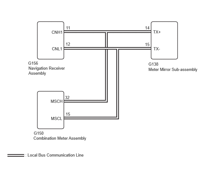
CAUTION / NOTICE / HINT
- NOTICE:
- ·
To measure the resistance of the CAN bus, turn the engine switch off, wait at least 1 minutes without operating any keys or switches or opening or closing the doors, disconnect the battery, wait at least 1 minutes again, and then measure the resistance.
·When disconnecting and reconnecting the battery
- HINT:
-
When disconnecting and reconnecting the battery, there is an automatic learning function that completes learning when the respective system is used.
- HINT:
- ·
When checking each connector, press the connector case in the direction of the connection before disconnecting the connectors, and check that there are no disconnections or looseness.
·When disconnecting the connectors, check that there is no damage, deformation, or corrosion of the connector terminals and connector case.
PROCEDURE
Check each system for DTCs.
- Body Electrical > Combination Meter > Trouble Codes
- 50001 409
- Body Electrical > Head Up Display > Trouble Codes
- 50001 408
| Pattern | DTC Output Part Name
(Display on GTS) |
|
|---|---|---|
| Combination Meter Assembly
(Combination Meter) |
Meter Mirror Sub-assembly
(Head Up Display) |
|
| Pattern 1 | B132187 | B132187 |
| Pattern 2 | - | B132187 |
- Result:
Result Proceed to Pattern 1 is output A Pattern 2 is output B
A
B
Disconnect the cable from the negative (-) battery terminal.
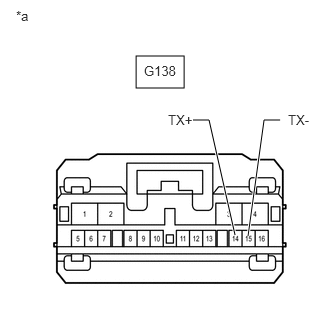
| *a | Front view of wire harness connector
(to Meter Mirror Sub-assembly) |
Disconnect the meter mirror sub-assembly connector.
Measure the resistance according to the value(s) in the table below.
- Standard Resistance:
Tester Connection Condition Specified Condition G138-14 (TX+) - G138-15 (TX-) Cable disconnected from negative (-) battery terminal 54 to 69 Ω
- Result:
Proceed to OK NG
OK
NG