☰ Toyota Wildlander☰ فهرستVehicle Interior › METER / GAUGE / DISPLAY › METER / GAUGE SYSTEM(for SFTM Made)
RM36D0EC
_58
Vehicle Interior
_083097
METER / GAUGE / DISPLAY
_0694858
METER / GAUGE SYSTEM(for SFTM Made)
J
METER / GAUGE / DISPLAY METER / GAUGE SYSTEM(for SFTM Made) Odo/Trip Switch Malfunction
DESCRIPTION
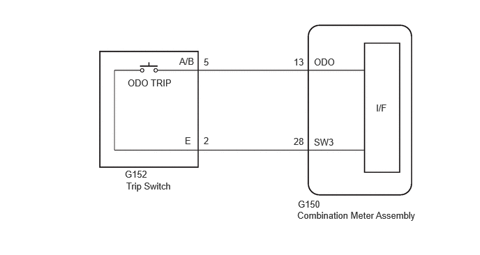
The ODO/TRIP display of the combination meter changes each time the trip switch is pressed.
WIRING DIAGRAM
4.438,3.135 6.302,3.354
1.865,0.219
10
false
Combination Meter Assembly
4.448,2.969 4.906,3.167
0.458,0.198
10
false
G150
5.615,1.531 6.073,1.729
0.458,0.198
10
false
I/F
2.677,0.833 3.135,1.031
0.458,0.198
10
false
A/B
2.76,2.021 2.958,2.219
0.198,0.198
10
false
E
3.042,0.844 3.198,1.042
0.156,0.198
10
false
5
4.385,0.844 4.604,1.073
0.219,0.229
10
false
13
3.042,2.021 3.198,2.219
0.156,0.198
10
false
2
4.688,0.844 5.146,1.042
0.458,0.198
10
false
ODO
1.865,2.521 2.323,2.719
0.458,0.198
10
false
G152
1.885,2.698 2.625,2.948
0.74,0.25
10
false
Trip Switch
1.906,1.156 2.625,1.344
0.719,0.188
10
false
ODO TRIP
4.688,2.042 5.146,2.24
0.458,0.198
10
false
SW3
4.385,2.031 4.604,2.26
0.219,0.229
10
false
28
CAUTION / NOTICE / HINT
- NOTICE:
-
When replacing the combination meter assembly, always replace it with a new one. If a combination meter assembly which was installed to another vehicle is used, the information stored in it will not match the information from the vehicle and a DTC may be stored.
PROCEDURE
1.READ VALUE USING GTS (ODO/TRIP CHANGE SWITCH)
a.
Using the GTS, read the Data List.
- Body Electrical > Combination Meter > Data List
-
Tester Display Measurement Item Range Normal Condition Diagnostic Note ODO/TRIP Change Switch ODO/TRIP switch (Trip switch) OFF or ON OFF: ODO/TRIP switch (trip switch) released
ON: ODO/TRIP switch (trip switch) pushed-
- Body Electrical > Combination Meter > Data List
-
Tester Display ODO/TRIP Change Switch - 50003 409 2
- OK:
TRIP switch condition displayed on the GTS changes with the actual switch operation.
- Result:
Proceed to OK NG
OK
REPLACE COMBINATION METER ASSEMBLY
NG
2.INSPECT TRIP SWITCH
2.INSPECT TRIP SWITCH
a.
Remove the trip switch.
b.
Inspect the trip switch.
- Result:
Proceed to OK NG
OK
3.CHECK HARNESS AND CONNECTOR (COMBINATION METER ASSEMBLY - TRIP SWITCH)
NG
REPLACE TRIP SWITCH
3.CHECK HARNESS AND CONNECTOR (COMBINATION METER ASSEMBLY - TRIP SWITCH)
a.
Disconnect the G150 combination meter assembly connector.
b.
Disconnect the G152 trip switch connector.
c.
Measure the resistance according to the value(s) in the table below.
- Standard Resistance:
Tester Connection Condition Specified Condition G150-13 (ODO) - G152-5 (A/B) Always Below 1 Ω G150-28 (SW3) - G152-2 (E) Always Below 1 Ω G150-13 (ODO) or G152-5 (A/B) - Body ground Always 10 kΩ or higher G150-28 (SW3) or G152-2 (E) - Body ground Always 10 kΩ or higher
- Result:
Proceed to OK NG
OK
REPLACE COMBINATION METER ASSEMBLY
NG
REPAIR OR REPLACE HARNESS OR CONNECTOR