NETWORKING CAN COMMUNICATION SYSTEM(for SFTM Made HV Model) SYSTEM DESCRIPTION
BRIEF DESCRIPTION
The Controller Area Network (CAN) is a serial data communication system for real time application. It is a vehicle multiplex communication system which has a high communication speed and the ability to detect malfunctions.
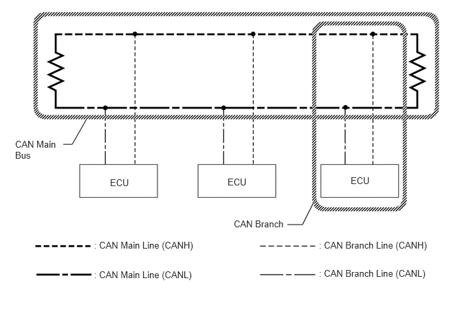
Using the CANH and CANL bus lines as a pair, CAN communication is performed using a voltage differential. (A base voltage is applied to the pair of lines and a voltage differential is created when communicating.)
Many ECUs or sensors installed to the vehicle operate by sharing information and communicating with each other.
2 resistors which are necessary for communication are used in a CAN bus main line.
DEFINITION OF TERMS
Central bus
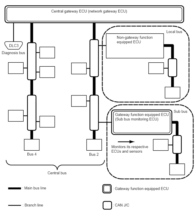
The central bus is a generic name for multiple subordinate CAN bus lines on the central gateway ECU (network gateway ECU).
- HINT:
-
A bus is displayed as Bus on the "Communication Bus Check" screen of the GTS.
Sub bus
A sub bus is a bus that has a gateway function equipped ECU in order to communicate with the central bus and other sub buses.
- HINT:
- ·
A sub bus is displayed as Sub bus on the "Communication Bus Check" screen of the GTS.
·When Sub bus is selected on the "Communication Bus Check" screen, ECUs and sensors connected to non-CAN networks such as LIN may also be displayed in addition to the ECUs and sensors connected to sub buses in the CAN network.
Local bus
A local bus is a bus that does not have the ability to communicate with other buses. ECUs and sensors on a local bus can only communicate with other ECUs and sensors on the same bus.
- NOTICE:
-
Gateway function not equipped ECU is a generic name for ECUs not connected to the central gateway ECU (network gateway ECU) with a gateway function.
CAN J/C
A CAN junction connector is a connector that connects branch lines to a main bus.
Main bus
A main bus line is the wire harness that runs between the 2 terminating resistors of a bus.
Branch
A branch line is a wire harness that connects an ECU or sensor to a main bus line.
Terminating resistors
Two resistors of 120 Ω are installed in parallel across the ends of the CAN main bus lines. They are called terminating resistors. These resistors allow the changes of the voltage differential between the CAN bus lines to be accurately judged. To allow proper function of CAN communication, it is necessary to have both terminating resistors installed. Since the two resistors are installed in parallel, this results in a measurement of approximately 60 Ω.