ALIGNMENT / HANDLING DIAGNOSIS REAR WHEEL ALIGNMENT ADJUSTMENT
CAUTION / NOTICE / HINT
The necessary procedures (adjustment, calibration, initialization, or registration) that must be performed after completing the rear wheel alignment procedure are shown below.
| Replaced Part or Performed Procedure | Necessary Procedure | Effect/Inoperative Function when Necessary Procedure not Performed | Link |
|---|---|---|---|
| Wheel alignment adjustment | 1.
Perform "Reset Memory". 2.
Perform "Calibration". |
·
DTCs are stored ·
ABS warning light illuminates ·
Brake warning light / yellow (minor malfunction) illuminates ·
Slip indicator light illuminates ·
VSC disabled or malfunctions |
( 202304,999999,_54,_083077,_0401811,RM1000000029TH7,) 202304,999999,_54,_083077,_0401811,RM1000000029TH7,)
|
| Replaced Part or Performed Procedure | Necessary Procedure | Effect/Inoperative Function when Necessary Procedure not Performed | Link |
|---|---|---|---|
| Wheel alignment adjustment | 1.
Perform "Reset Memory". 2.
Perform acceleration sensor zero point calibration and store system information memorization. |
·
VSC is disabled or malfunctions ·
DTCs are output ·
Slip indicator light illuminates ·
ABS warning light illuminates |
(202304,999999,_54,_083077,_0402316,RM100000002AG8P,)
|
PROCEDURE

 1.INSPECT TIRES
2.MEASURE VEHICLE HEIGHT
3.INSPECT CAMBER
- NOTICE:
-
Inspect while the vehicle is unloaded.
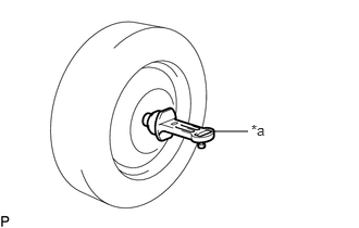
| *a | Camber-caster-kingpin Gauge |
Install a camber-caster-kingpin gauge.
Inspect the camber.
- Camber (Unloaded Vehicle):
Tire Size Camber Inclination Right-left Difference 225/65R17 -1°20' +/-45' (-1.33° +/-0.75°) 0°45' (0.75°) or less 225/60R18 -1°20' +/-45' (-1.33° +/-0.75°) 235/55R19 -1°20' +/-45' (-1.33° +/-0.75°)
- HINT:
-
Camber is not adjustable. If the measurement is not within the specified range, inspect the suspension parts for damage and/or wear, and replace them if necessary.
4.INSPECT TOE-IN
- NOTICE:
-
Inspect while the vehicle is unloaded.
Bounce the vehicle up and down at the corners to stabilize the suspension.
Release the parking brake and move the shift lever to N (for CVT, Automatic transaxle, Hybrid Transaxle).
Release the parking brake and move the shift lever to neutral (for Manual Transaxle).
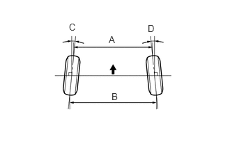
Push the vehicle straight ahead approximately 5 m (16.4 ft.). (Step A)
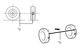
| *a | Tread Center Mark |
| *b | Dimension B |

|
Front of the Vehicle |
Put tread center marks on the rearmost points of the rear wheels and measure the distance between the marks (dimension B).
Slowly push the vehicle straight ahead to cause the rear wheels to rotate 180°. Use the rear tire valve as a reference point.
- HINT:
-
Do not allow the wheels to rotate more than 180°. If the wheels rotate more than 180°, perform the procedure from step A again.
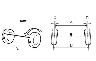
| *a | Dimension A |
|
|
Front of the Vehicle |
Measure the distance between the tread center marks on the front of the rear wheels (dimension A).
- Toe-in (Unloaded Vehicle):
Tire Size Specified Condition 225/65R17 C + D: 0°14' +/- 0°10' (0.23° +/- 0.17°) B - A: 2.6 +/-2.0 mm (0.10 +/-0.08 in.) 225/60R18 C + D: 0°13' +/- 0°10' (0.22° +/- 0.17°) B - A: 2.6 +/-2.0 mm (0.10 +/-0.08 in.) 235/55R19 C + D: 0°14' +/- 0°10' (0.23° +/- 0.17°) B - A: 2.7 +/-2.0 mm (0.11 +/-0.08 in.)
- HINT:
-
Measure "B - A" only when "C + D" cannot be measured.
If the toe-in is not within the specified range, adjust it at the rear suspension toe adjust cam sub-assembly.
5.ADJUST TOE-IN
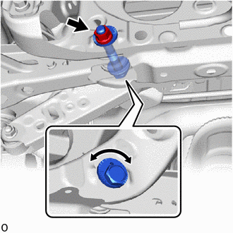
Loosen the nut of the rear No. 2 suspension arm assembly (on the rear suspension member sub-assembly side).
- NOTICE:
-
Hold the rear suspension toe adjust cam sub-assembly while rotating the nut.
|
|
Front of the Vehicle |
Rotate the rear suspension toe adjust cam sub-assembly to adjust the toe-in.
- Toe-in (Unloaded Vehicle):
Tire Size Specified Condition 225/65R17 C + D: 0°14' +/- 0°10' (0.23° +/- 0.17°) B - A: 2.6 +/-2.0 mm (0.1 +/-0.08 in.) 225/60R18 C + D: 0°13' +/- 0°10' (0.22° +/- 0.17°) B - A: 2.6 +/-2.0 mm (0.1 +/-0.08 in.) 235/55R19 C + D: 0°14' +/- 0°10' (0.23° +/- 0.17°) B - A: 2.7 +/-2.0 mm (0.11 +/-0.08 in.)
- HINT:
- ·
Rotating the rear suspension toe adjust cam sub-assembly by one notch changes the toe by approximately 2.8 mm (0.112 in.).
·Perform adjustments so that the value is as close as possible to the median of the specified range.
Tighten the nut of the rear No. 2 suspension arm assembly (on the rear suspension member sub-assembly side).
- Torque:
- 100 N*m (1020 kgf*cm, 74 ft.*lbf)
- NOTICE:
-
Hold the rear suspension toe adjust cam sub-assembly while rotating the nut.
6. ALIGN FRONT WHEELS FACING STRAIGHT AHEAD
7. PERFORM YAW RATE AND ACCELERATION SENSOR ZERO POINT CALIBRATION (for HV Model)
8. PERFORM ACCELERATION SENSOR ZERO POINT CALIBRATION AND STORE SYSTEM INFORMATION MEMORIZATION (for Gasoline Model)