BRAKE SYSTEM (OTHER) BRAKE BOOSTER(for Gasoline Model) INSTALLATION
PROCEDURE

 44785D
1.INSTALL BRAKE MASTER CYLINDER GASKET
44785D
1.INSTALL BRAKE MASTER CYLINDER GASKET
Install a new brake booster gasket to the brake booster assembly.
44610
2.INSTALL BRAKE BOOSTER ASSEMBLY
Temporarily install the brake booster assembly to the vehicle body.
- NOTICE:
-
Do not apply excessive force to the brake lines.
Temporarily install the lock nut and brake master cylinder push rod clevis to the brake booster assembly.
- NOTICE:
-
Tighten the lock nut when adjusting the brake pedal height.
Install the 4 nuts to secure the brake booster assembly.
- Torque:
- 12.7 N*m (130 kgf*cm, 9 ft.*lbf)
Install a new brake tube clamp to the vehicle body with the bolt.
- Torque:
- 7.0 N*m (71 kgf*cm, 62 in.*lbf)
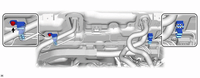
Engage the clamp and install a new brake tube clamp to the vehicle body.
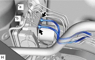
| *a | From 1st Chamber of Brake Master Cylinder Sub-assembly |
| *b | From 2nd Chamber of Brake Master Cylinder Sub-assembly |
Temporarily install each brake line to the correct position on the brake actuator assembly as shown in the illustration.
- NOTICE:
- ·
Do not kink or damage the brake line.
·Do not allow any foreign matter such as dirt or dust to enter the brake line from the connecting parts.
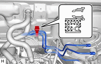
Engage the 3 clamps to connect the brake tube clamp to the brake lines.
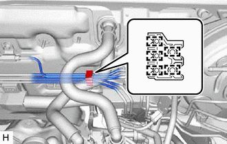
Engage the 5 clamps to install a new brake tube clamp to the brake lines.
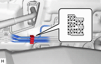
Engage the 5 clamps to install a new brake tube clamp to the brake lines.
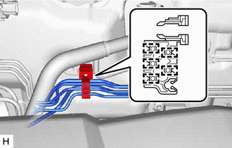
Engage the 5 clamps to connect the brake tube clamp to the brake lines.
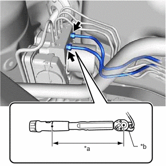
| *a | Torque Wrench Fulcrum Length |
| *b | Union Nut Wrench |
Using a union nut wrench, connect the 2 brake lines to the brake actuator assembly.
- Torque:
- Specified tightening torque : 19.5 N*m (199 kgf*cm, 14 ft.*lbf)
- NOTICE:
- ·
Do not kink or damage the brake lines.
·Do not allow the brake lines to twist or interfere with other parts or the vehicle body during tightening.
·Do not allow any foreign matter such as dirt or dust to enter the brake lines from the connecting parts.
- HINT:
- ·
Calculate the torque wrench reading when changing the fulcrum length of the torque wrench.
·When using a union nut wrench (fulcrum length of 20 mm (0.787 in.)) + torque wrench (fulcrum length of 162 mm (6.38 in.)):
17.4 N*m (177 kgf*cm, 13 ft.*lbf)
Connect the connector to the vacuum sensor assembly.
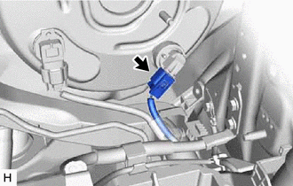
for Type A
Connect the connector to the vacuum warning switch assembly.
Remove the protective tape.
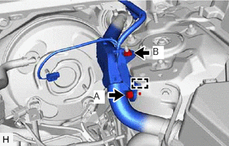
Engage the guide and connect the wire harness.
Install the bolt (A) and nut (B) to secure the wire harness.
- Torque:
- Bolt (A) : 8.0 N*m (82 kgf*cm, 71 in.*lbf)
- Nut (B) : 12.5 N*m (127 kgf*cm, 9 ft.*lbf)
44773F
3.INSTALL UNION TO CHECK VALVE HOSE
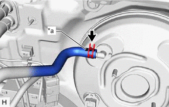
| *a | Paint Mark |
Connect the check valve to connector tube hose to the brake booster assembly and slide the clip to secure it.
- NOTICE:
- ·
When connecting the check valve to connector tube hose, face the paint mark up.
·Make sure that the tabs of the clip are facing upward.
47264A
4.INSTALL PUSH ROD PIN
5.CONNECT WIRE HARNESS
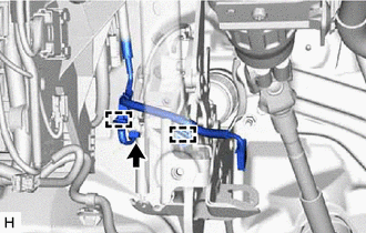
Engage the 2 clamps to connect the wire harness to the brake pedal support assembly.
Connect the connector.
47101A
6.INSTALL BRAKE PEDAL RETURN SPRING
87201B
7.INSTALL NO. 2 AIR DUCT SUB-ASSEMBLY
73900
8.INSTALL LOWER NO. 1 INSTRUMENT PANEL AIRBAG ASSEMBLY
74404B
9.INSTALL BATTERY CLAMP SUB-ASSEMBLY
89661
10.INSTALL ECM
11.INSTALL BATTERY
47201
12.INSTALL BRAKE MASTER CYLINDER SUB-ASSEMBLY
13.INSPECT AND ADJUST BRAKE PEDAL