BRAKE (FRONT) FRONT BRAKE INSTALLATION
CAUTION / NOTICE / HINT
- NOTICE:
- ·
Immediately after installing the brake pads, the braking performance may be reduced. Always perform a road test in a safe place while paying attention to the surroundings.
·After replacing the front disc brake pads, the brake pedal may feel soft due to clearance between the front disc brake pads and front disc. Depress the brake pedal several times until the brake pedal feels firm.
·After replacing the front disc brake pads, always perform a road test to check the braking performance and check for vibrations.
·When removing or installing the front disc brake cylinder assembly, pushing back the disc brake piston may cause a large clearance between the brake pads and brake disc. When the brake pedal is depressed with a large clearance between the brake pads and the brake disc, DTC C140000 and/or C140A00 related to abnormal brake fluid pressure may be stored. Make sure to clear any DTCs after performing this procedure. (for HV Model)
·While the auxiliary battery is connected, even if the ignition switch is off, the brake control system activates when the brake pedal is depressed or any door courtesy switch turns on. Therefore, when servicing the brake system components, do not operate the brake pedal or open/close the doors while the auxiliary battery is connected. (for HV Model)
- HINT:
- ·
Use the same procedure for the RH and LH sides.
·The following procedure is for the LH side.
PROCEDURE

 43512
1.INSTALL FRONT DISC
43512
1.INSTALL FRONT DISC
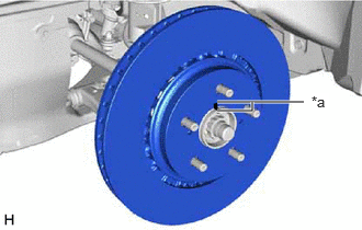
| *a | Matchmark |
Align the matchmarks of the front disc and front axle hub sub-assembly, and install the front disc.
- NOTICE:
-
When replacing the front disc with a new one, select the installation position where the front disc has minimal runout.
47722
2.INSTALL FRONT DISC BRAKE CYLINDER MOUNTING
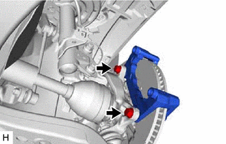
Install the front disc brake cylinder mounting to the steering knuckle with the 2 bolts.
- Torque:
- for Steel Steering Knuckle : 107 N*m (1091 kgf*cm, 79 ft.*lbf)
- for Aluminum Steering Knuckle : 150 N*m (1530 kgf*cm, 111 ft.*lbf)
3.INSTALL FRONT DISC BRAKE BUSHING DUST BOOT
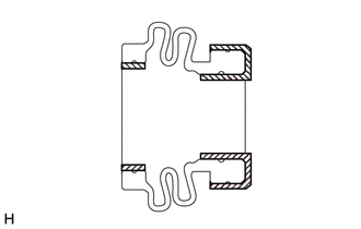

|
Lithium Soap Base Glycol Grease |
Apply a thin layer of lithium soap base glycol grease to the entire circumference of 2 new front disc brake bushing dust boots.
- HINT:
-
Apply more than 0.3 g (0.01 oz) of lithium soap base glycol grease to each front disc brake bushing dust boot.
Install the 2 front disc brake bushing dust boots to the front disc brake cylinder mounting.
4.INSTALL FRONT DISC BRAKE CYLINDER SLIDE PIN
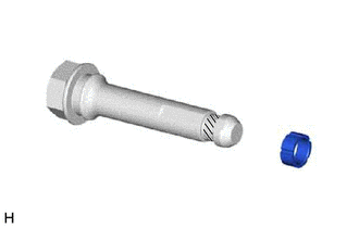
|
|
Lithium Soap Base Glycol Grease |
Apply a thin layer of lithium soap base glycol grease to the contact surface of the front disc brake cylinder slide pin (lower side).
Install a new front disc brake cylinder slide bushing to the front disc brake cylinder slide pin (lower side).
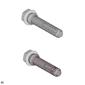
|
|
Lithium Soap Base Glycol Grease |
Apply a thin layer of lithium soap base glycol grease to the sliding part and the sealing surfaces of the 2 front disc brake cylinder slide pins.
Install the 2 front disc brake cylinder slide pins to the front disc brake cylinder mounting.
Push each front disc brake cylinder slide pin into the front disc brake bushing dust boot to engage the pin to the boot.
5.INSTALL FRONT DISC BRAKE PAD SUPPORT PLATE
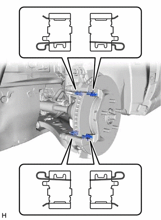
Install the 4 front disc brake pad support plates to the front disc brake cylinder mounting.
- NOTICE:
-
Be sure to install each front disc brake pad support plate in the correct position and direction.
04945
6.INSTALL FRONT DISC BRAKE ANTI-SQUEAL SHIM KIT
7.INSTALL FRONT DISC BRAKE PAD
Install the 2 front disc brake pads to the front disc brake cylinder mounting.
- NOTICE:
- ·
Keep the friction surfaces of the front disc brake pads and front disc free from oil and grease.
·Install the front disc brake pad so that the pad wear indicator plate is mounted on the upper side of the vehicle.
47750
8.INSTALL FRONT DISC BRAKE CYLINDER ASSEMBLY
Hold each front disc brake cylinder slide pin and install the front disc brake cylinder assembly to the front disc brake cylinder mounting with the 2 bolts.
- Torque:
- 34.3 N*m (350 kgf*cm, 25 ft.*lbf)
47313J
9.CONNECT FRONT FLEXIBLE HOSE

Connect the front flexible hose to the front disc brake cylinder assembly with a new union bolt and a new gasket.
- Torque:
- 29.4 N*m (300 kgf*cm, 22 ft.*lbf)
- NOTICE:
-
Install the front flexible hose lock securely into the lock hole in the front disc brake cylinder assembly.
10.CONNECT CABLE TO NEGATIVE AUXILIARY BATTERY TERMINAL (for HV Model)
11.BLEED BRAKE LINE
for Gasoline Model: Click hereBrake>BRAKE SYSTEM (OTHER)>BRAKE FLUID (for Gasoline Model)>BLEEDING201910,999999,_54,_083078,_0403143,RM100000001JO73,
12.INSTALL FRONT WHEEL
13. INITIALIZATION AFTER RECONNECTING AUXILIARY BATTERY TERMINAL (for HV Model)
- HINT:
-
When disconnecting and reconnecting the auxiliary battery, there is an automatic learning function that completes learning when the respective system is used.