STEERING COLUMN STEERING COLUMN ASSEMBLY DISASSEMBLY
CAUTION / NOTICE / HINT
- NOTICE:
- ·
When using a vise, place aluminum plates between the part and vise.
·When using a vise, do not overtighten it.
PROCEDURE

 45020B
1.REMOVE STEERING LOCK ACTUATOR OR UPPER BRACKET ASSEMBLY (w/o Entry and Start System)
45020B
1.REMOVE STEERING LOCK ACTUATOR OR UPPER BRACKET ASSEMBLY (w/o Entry and Start System)
Using a 3 mm pin punch, mark the center of the tapered-head bolt.
Using a 3 to 4 mm drill bit, drill into the tapered-head bolt.
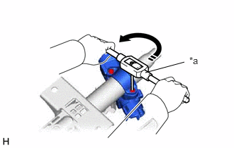
| *a | Screw Extractor |
Using a screw extractor, remove the bolt and steering column upper with switch bracket.
69057A
2.REMOVE IGNITION SWITCH LOCK CYLINDER ASSEMBLY (w/o Entry and Start System)

| *1 | ACC |
| *a | Push |
| *b | Pull |
Turn the ignition switch to ACC.
Insert the tip of a screwdriver into the hole in the steering column upper bracket as shown in the illustration, and pull the ignition switch lock cylinder out until its claw comes into contact with the stopper of the steering column upper bracket.
- NOTICE:
-
Pull the ignition switch lock cylinder assembly out until its claw comes into contact with the stopper of the steering column upper bracket assembly. Otherwise, the following procedure cannot be conducted properly.
84052
3.REMOVE UN-LOCK WARNING SWITCH ASSEMBLY (w/o Entry and Start System)
84450
4.REMOVE IGNITION OR STARTER SWITCH ASSEMBLY (w/o Entry and Start System)