AXLE AND DIFFERENTIAL FRONT AXLE HUB ON-VEHICLE INSPECTION
CAUTION / NOTICE / HINT
- HINT:
- ·
Use the same procedure for the RH and LH sides.
·The following procedure is for the LH side.
PROCEDURE

 1. PRECAUTION (for HV Model)
- NOTICE:
-
After the ignition switch is turned off, there may be a waiting time before disconnecting the negative (-) auxiliary battery terminal.
2.DISABLE BRAKE CONTROL (for HV Model)
3.REMOVE FRONT WHEEL
47313J
4.DISCONNECT FRONT FLEXIBLE HOSE
5.DISCONNECT FRONT DISC BRAKE CALIPER ASSEMBLY LH
43512
6.REMOVE FRONT DISC
7.INSPECT FRONT AXLE HUB BEARING LOOSENESS
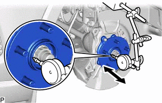
Using a dial indicator with magnetic base, check for looseness near the center of the front axle hub sub-assembly.
- Maximum looseness:
0.05 mm (0.00197 in.)
- NOTICE:
- ·
Ensure that the dial indicator is set perpendicular to the measurement surface.
·Keep the magnet of the dial indicator away from the front axle hub sub-assembly and front speed sensor.
- HINT:
-
If the looseness exceeds the maximum, replace the front axle hub sub-assembly.
8.INSPECT FRONT AXLE HUB RUNOUT

Using a dial indicator with magnetic base, check for runout on the surface of the front axle hub sub-assembly outside the front axle hub bolts.
- Maximum runout:
0.05 mm (0.00197 in.)
- NOTICE:
- ·
Ensure that the dial indicator is set perpendicular to the measurement surface.
·Make sure to set the tip of the dial indicator towards the outside of the front axle hub bolts.
·Keep the magnet of the dial indicator away from the front axle hub sub-assembly and front speed sensor.
- HINT:
-
If the runout exceeds the maximum, replace the front axle hub sub-assembly.
43512
9.INSTALL FRONT DISC
10.INSTALL FRONT DISC BRAKE CALIPER ASSEMBLY LH
47313J
11.INSTALL FRONT FLEXIBLE HOSE
12.INSTALL FRONT WHEEL
13.CONNECT CABLE TO NEGATIVE AUXILIARY BATTERY TERMINAL (for HV Model)
14. INITIALIZATION AFTER RECONNECTING AUXILIARY BATTERY TERMINAL (for HV Model)
- HINT:
-
When disconnecting and reconnecting the auxiliary battery, there is an automatic learning function that completes learning when the respective system is used.