M20C-FKS ENGINE CONTROL CAMSHAFT TIMING CONTROL MOTOR INSTALLATION
CAUTION / NOTICE / HINT
- NOTICE:
-
This procedure includes the installation of small-head bolts. Refer to Small-Head Bolts of Basic Repair Hint to identify the small-head bolts.
- HINT:
-
Perform "Inspection After Repair" after removing and installing, or replacing the cam timing control motor with EDU assembly.
PROCEDURE

 13090D
1.INSTALL CAM TIMING CONTROL MOTOR WITH EDU ASSEMBLY
13090D
1.INSTALL CAM TIMING CONTROL MOTOR WITH EDU ASSEMBLY
- HINT:
-
Perform "Inspection After Repair" after removing and installing, or replacing the cam timing control motor with EDU assembly.
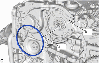
| *a | Protrusion |
| *b | Groove |
Install a new cam timing control motor O-ring to the No. 2 timing chain cover assembly with the protrusion of the cam timing control motor O-ring oriented as shown in the illustration.
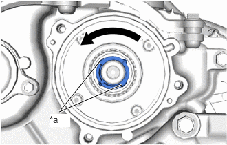
| *a | Cutout |
Turn the cutout of the camshaft timing gear assembly eccentric shaft counterclockwise by hand, and set it to the maximum retard angle position.
- HINT:
- ·
If a camshaft lobe is opening a valve, the eccentric shaft will be difficult to turn.
·When the cutout of the camshaft timing gear assembly eccentric shaft cannot be turned any farther, it is set to the maximum retard angle.
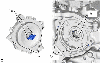
| *a | Joint |
| *b | Cutout |
| *c | Pin Hole |
| *d | Knock Pin |
Install the cam timing control motor with EDU assembly to the No. 2 timing chain cover assembly.
- NOTICE:
- ·
When installing, align the joints of the cam timing control motor with EDU assembly with the cutouts of the camshaft timing gear assembly eccentric shaft.
·Align the pin holes of the cam timing control motor with EDU assembly with the knock pins of the No. 2 timing chain cover assembly when installing the cam timing control motor with EDU assembly.
·Make sure the contact surface of the cam timing control motor with EDU assembly (the surface that contacts the No. 2 timing chain cover assembly) is free of foreign matter.
·When installing the cam timing control motor with EDU assembly, do not use excessive force.
·If the cam timing control motor with EDU assembly has been struck or dropped, replace it.
·Do not disassemble the cam timing control motor with EDU assembly. If disassembled, replace it.
Install the 3 bolts.
- Torque:
- 21 N*m (214 kgf*cm, 15 ft.*lbf)
Connect the cam timing control motor with EDU assembly connector.
Connect the No. 2 ground wire to the engine mounting insulator sub-assembly RH with the bolt.
- Torque:
- 10 N*m (102 kgf*cm, 7 ft.*lbf)
2.CONNECT CABLE TO NEGATIVE BATTERY TERMINAL
3.INSPECT FOR ENGINE OIL LEAK
12601B
4.INSTALL NO. 1 ENGINE COVER SUB-ASSEMBLY
5. INITIALIZATION AFTER RECONNECTING BATTERY TERMINAL
- HINT:
-
When disconnecting and reconnecting the battery, there is an automatic learning function that completes learning when the respective system is used.