DRIVE SHAFT / PROPELLER SHAFT FRONT DRIVE SHAFT ASSEMBLY(for AWD) REMOVAL
CAUTION / NOTICE / HINT
The necessary procedures (adjustment, calibration, initialization, or registration) that must be performed after parts are removed and installed, or replaced during front drive shaft assembly removal/installation are shown below.
| Replaced Part or Performed Procedure | Necessary Procedure | Effect/Inoperative Function when Necessary Procedure not Performed | Link |
|---|---|---|---|
| Front wheel alignment adjustment | ·
Clear the zero point calibration data and stored linear solenoid valve calibration data. ·
Perform initialization and calibration of the linear solenoid valve. ·
Perform yaw rate and acceleration sensor zero point calibration. |
·
DTCs are stored ·
ABS warning light illuminates ·
Brake warning light / yellow (minor malfunction) illuminates ·
Slip indicator light illuminates ·
VSC disabled or malfunctions |
( 202304,999999,_54,_083077,_0401811,RM1000000029TH7,) 202304,999999,_54,_083077,_0401811,RM1000000029TH7,)
|
| Replaced Part or Performed Procedure | Necessary Procedure | Effect/Inoperative Function when Necessary Procedure not Performed | Link |
|---|---|---|---|
| Front wheel alignment adjustment | ·
Perform reset memory ·
Perform acceleration sensor zero point calibration and store system information memorization. |
·
VSC is disabled or malfunctions ·
DTCs are output ·
Slip indicator light illuminates ·
ABS warning light illuminates |
(202304,999999,_54,_083077,_0402316,RM100000002AG8P,)
|
| CVT fluid | ATF thermal degradation estimate reset | The value of the Data List item "ATF Thermal Degradation Estimate" is not estimated correctly | (202304,202405,_52,_138817,_0596468,RM100000002AWR9,202405,202409,_52,_138817,_0596468,RM100000002JJ5Q,202409,999999,_52,_138817,_0596468,RM100000002NRBH,)
|
| Air bleed oil pump with motor assembly (w/ Stop and Start System) | Stop and start system | (202304,202409,_51,_083056,_0402418,RM1000000029CS9,202409,999999,_51,_083056,_0402418,RM100000002NSFT,)
|
- HINT:
- ·
Use the same procedure for the RH and LH sides.
·The following procedure is for the LH side.
PROCEDURE

 1.REMOVE FRONT WHEEL
51420
2.REMOVE NO. 2 ENGINE UNDER COVER ASSEMBLY
53737D
3.REMOVE FRONT FENDER APRON SEAL LH
53736E
4.REMOVE FRONT FENDER APRON SEAL RH
5.DRAIN TRANSAXLE OIL
for Hybrid Vehicle Transaxle: Click hereGeneral>MAINTENANCE>P710 HYBRID TRANSAXLE FLUID>REPLACEMENT202104,999999,_V1,_083136,_0400798,RM100000001WHMW,
6.DRAIN TRANSFER OIL
43502H
7.REMOVE FRONT AXLE SHAFT NUT LH
43501H
8.REMOVE FRONT AXLE SHAFT NUT RH
- HINT:
-
Use the same procedure described for the LH side.
9.DISCONNECT FRONT SPEED SENSOR LH
10.DISCONNECT FRONT SPEED SENSOR RH
- HINT:
-
Use the same procedure described for the LH side.
48810
11.DISCONNECT FRONT STABILIZER LINK ASSEMBLY LH
48820B
12.DISCONNECT FRONT STABILIZER LINK ASSEMBLY RH
- HINT:
-
Use the same procedure described for the LH side.
48069
13.DISCONNECT FRONT LOWER NO. 1 SUSPENSION ARM SUB-ASSEMBLY LH
48068
14.DISCONNECT FRONT LOWER NO. 1 SUSPENSION ARM SUB-ASSEMBLY RH
- HINT:
-
Use the same procedure described for the LH side.
15.DISCONNECT STEERING KNUCKLE WITH AXLE HUB LH
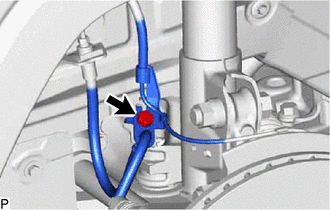
Remove the bolt and disconnect the front speed sensor and front flexible hose from the front shock absorber assembly.
- NOTICE:
-
Be sure to separate the front speed sensor and front flexible hose from the front shock absorber assembly completely.
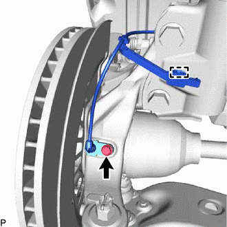
Remove the bolt, disengage the clamp and disconnect the front speed sensor from the front shock absorber assembly and steering knuckle.
- NOTICE:
- ·
Prevent foreign matter from contacting the sensor tip.
·Be careful not to damage the front speed sensor.
·Clean the speed sensor installation hole and the contact surfaces every time the front speed sensor is removed.
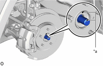
| *a | Matchmark |
Put matchmarks on the front drive shaft assembly and front axle hub sub-assembly.
- NOTICE:
-
Do not use a punch to make the matchmarks.
Using a plastic hammer, disconnect the front drive shaft assembly from the steering knuckle with axle hub.
- NOTICE:
- ·
Be careful not to damage the boot and drive shaft dust cover.
·Do not excessively push out the drive shaft from the front axle hub.
16.DISCONNECT STEERING KNUCKLE WITH AXLE HUB RH
- HINT:
-
Use the same procedure described for the LH side.
43420
17.REMOVE FRONT DRIVE SHAFT ASSEMBLY LH
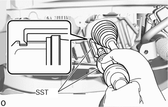
Using SST, remove the front drive shaft assembly LH.
- SST
- 09520-01011
09520-20010 (09521-02040, 09521-02010, 09521-02060)
- NOTICE:
- ·
Do not damage the front drive shaft oil seal LH, front axle inboard joint boot and front drive shaft dust cover LH.
·Do not drop the front drive shaft assembly LH.
·When carrying the front drive shaft assembly LH, hold it horizontally.
43410
18.REMOVE FRONT DRIVE SHAFT ASSEMBLY RH
for Gasoline model:
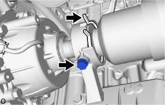
Disconnect the drive shaft bearing bracket hole snap ring from the drive shaft bearing bracket.
Remove the bolt and front drive shaft assembly RH from the drive shaft bearing bracket.
- NOTICE:
- ·
Do not damage the front drive shaft oil seal RH, transfer case oil seal RH, front axle inboard joint boot and front drive shaft dust cover RH.
·Do not drop the front drive shaft assembly RH.
·When carrying the front drive shaft assembly RH, hold it horizontally.
Remove the drive shaft bearing bracket hole snap ring from the front drive shaft assembly RH.
for HV model:
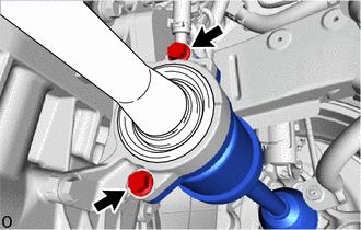
Remove the 2 bolts and pull out the front drive shaft assembly RH together with the drive shaft bearing case sub-assembly.
Remove the front drive shaft assembly RH from the transaxle.
- NOTICE:
- ·
Do not damage the front drive shaft oil seal RH, front axle inboard joint boot and front drive shaft dust cover RH.
·Do not drop the front drive shaft assembly RH.
·When carrying the front drive shaft assembly RH, hold it horizontally.
- HINT:
-
If the spline connection is stiff, using a brass bar and hammer, lightly tap the inboard joint assembly to remove it.
43420G
19.REMOVE FRONT DRIVE SHAFT HOLE SNAP RING LH
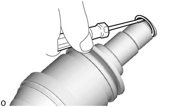
Using a screwdriver, remove the front drive shaft hole snap ring LH.