RM36D0EC
_58
Vehicle Interior
_083095
LIGHTING (INT)
_0400587
PERSONAL LIGHT
G
LIGHTING (INT) PERSONAL LIGHT INSPECTION
PROCEDURE

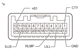
 1.INSPECT MAP LIGHT ASSEMBLY
a.
2.979,1.948 2.813,1.948
2.813,1.948 2.74,1.365
true
0.667,1 1.031,0.344
1.031,0.344 1.281,0.344
true
0.875,1.344 0.677,1.969
0.677,1.969 0.51,1.969
true
2.375,1.344 2.323,1.969
2.323,1.969 2.156,1.969
true
2.729,1.01 2.823,0.323
2.823,0.323 2.979,0.323
true
2.156,1.375 1.656,1.958
1.656,1.958 1.49,1.958
true
0.073,0.083 0.385,0.281
0.313,0.198
10
false
*a
1.344,0.271 1.719,0.51
0.375,0.24
10
false
+B1
3.021,1.854 3.396,2.094
0.375,0.24
10
false
GND
0.208,1.875 0.583,2.115
0.375,0.24
10
false
ILLB
1.885,1.875 2.26,2.115
0.375,0.24
10
false
LILL
3.042,0.24 3.417,0.479
0.375,0.24
10
false
CTY
1.073,1.854 1.583,2.094
0.51,0.24
10
false
RLMP
| *a | Component without harness connected
(Map Light Assembly) |
Inspect the map light.
Apply auxiliary battery voltage to the connector and check the light illumination condition.
- Standard Resistance:
Tester Connection Switch Condition Specified Condition 12 (+B1) - Auxiliary battery positive (+)
13 (GND) - Auxiliary battery negative (-)Map light switch LH ON Map light LH illuminates Map light switch RH ON Map light RH illuminates Dome light switch ON Map light LH and RH illuminates
If the result is not as specified, replace the map light assembly.
b.
Inspect the door switch.
Measure the resistance according to the value(s) in the table below.
- Standard Resistance:
Tester Connection Switch Condition Specified Condition 1 (CTY) - 16 (RLMP) Door switch OFF 10 kΩ or higher Door switch ON Below 1 Ω
If the result is not as specified, replace the map light assembly.
c.
Inspect the switch illumination.
Apply auxiliary battery voltage to the connector and check the light illumination condition.
- OK:
Tester Connection Condition Specified Condition 23 (ILLB) - Auxiliary battery positive (+)
15 (LILL) - Auxiliary battery negative (-)Always Illuminates
If the result is not as specified, replace the map light assembly.