PARK ASSIST / MONITORING TELEVISION CAMERA(for Front) INSTALLATION
CAUTION / NOTICE / HINT
- HINT:
-
A bolt without a torque specification is shown in the standard bolt chart.
PROCEDURE

 86790B
1.INSTALL FRONT TELEVISION CAMERA ASSEMBLY
86790B
1.INSTALL FRONT TELEVISION CAMERA ASSEMBLY
Attach the guide and temporarily install the front television camera assembly.
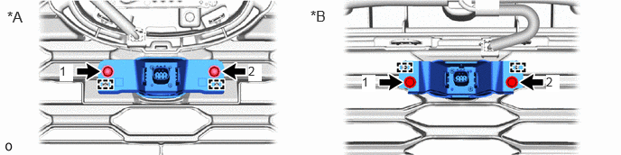
| *A | for Type A | *B | for Type B |
Install the front television camera assembly with the 2 screws.
- HINT:
-
Tighten the screws in the order shown in the illustration.
Connect the connector.
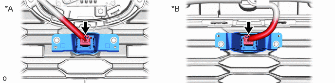
| *A | for Type A | *B | for Type B |
16681A
2.INSTALL RADIATOR UPPER AIR GUIDE PLATE
Place your hands at the position shown in the illustration and lift up the front bumper cover to the point where the radiator upper air guide plate can be installed.
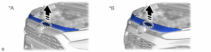
| *A | for Type A | *B | for Type B |

|
Place Hands Here | 
|
Pull in this Direction |
Install the radiator upper air guide plate as shown in the illustration.
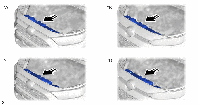
| *A | for Type A, Gasoline Model | *B | for Type B, Gasoline Model |
| *C | for Type A, HV Model | *D | for Type B, HV Model |
|
|
Install in this Direction | - | - |
Install the 4 bolts.
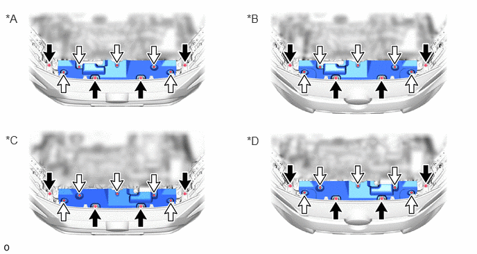
| *A | for Type A, Gasoline Model | *B | for Type B, Gasoline Model |
| *C | for Type A, HV Model | *D | for Type B, HV Model |

|
Bolt | 
|
Clip |
Install the 5 clips.
53510
3.INSTALL HOOD LOCK ASSEMBLY
17751
4.INSTALL NO. 1 INLET AIR CLEANER (for Gasoline Model)
86790B
5.ADJUST FRONT TELEVISION CAMERA ASSEMBLY
53301
6.INSPECT FITTING OF HOOD SUB-ASSEMBLY